TMM4175 Polymer Composites
Thick laminates and sandwich structures
Basic concepts
Bending and twist stiffness of plate of beam is proportional to the cube of the thickness, $h^3$. Hence, there is often a significant motivation for maximizing the thickness of shell-like structures. When the thickness increases relatively to lateral characteristic dimensions, the transverse shear deformation, which is neglected in classical laminate theory, becomes significant.
The shear contribution is particularly pronounced when the transverse stiffness is low compared to the in-plane stiffness. This is exceptionally true for sandwich structures having high-modulus fiber composite face sheets combined with a low density, low modulus core material. For these structures, the transverse shear deformation must most of the times be included for realistic estimations of out-of-plane deformation.
Examples
From Effective properties of laminates: the bending stiffness along the x-axis when $D_{xs}=D_{ys}=0$ is:
\begin{equation} D_b = b\big ( D_{xx} - \frac{D_{xy}^2}{D_{yy}} \big) \tag{1} \end{equation}m1= {"name": "E-glass/Epoxy", "rho": 2000E-12, "E1": 40000, "E2": 10000,
"v12": 0.3, "G12": 3800, "G13": 3800, "G23": 3400}
from laminatelib import laminateStiffnessMatrix
def bendingStiffness(layup,b=1):
# bending stiffness according to equation (1)
ADB = laminateStiffnessMatrix(layup)
return ADB[3,3] - (ADB[3,4]**2)/ADB[4,4]
When increasing the thickness by a factor two, the bending stiffness increases by a factor eight:
layup1 = [{'mat':m1, 'ori':0, 'thi':1},]
layup2 = [{'mat':m1, 'ori':0, 'thi':2},]

bendingStiffness(layup2)/bendingStiffness(layup1)
The effect is identical for laminates where all layer thicknesses are scaled identically:
layup3 = [{'mat':m1, 'ori':0, 'thi': 1},
          {'mat':m1, 'ori':90, 'thi':1},
          {'mat':m1, 'ori':0, 'thi': 1} ]

layup4 = [{'mat':m1, 'ori':0, 'thi': 2},
          {'mat':m1, 'ori':90, 'thi':2},
          {'mat':m1, 'ori':0, 'thi': 2} ]
bendingStiffness(layup4)/bendingStiffness(layup3)
The significance of transverse shear
Recall that the assumptions for the laminate theory neglect the transverse (or out-of-plane) shear stresses $\tau_{xz}$ and $\tau_{yz}$ as well as the shear strains $\gamma_{xz}$ and $\gamma_{yz}$.
For simplicity, we shall limit the initial discussion to beams with homogenous cross sections.
Consider 3-point bending of a beam with a rectangular cross section:
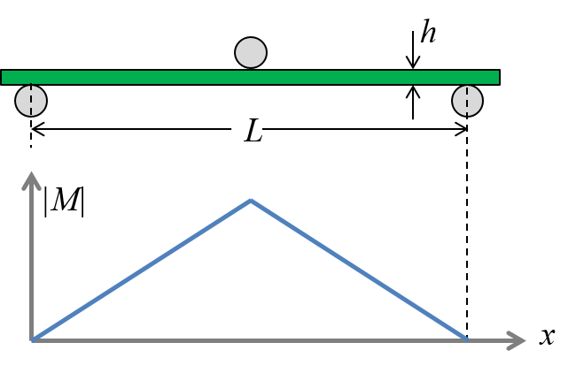
Figure-1: 3-point bending
The deflection of a freely supported beam subjected to 3-point bending according to the Euler-Bernoulli beam theory (based on the Kirchhoff assumptions, also being the basis for the laminate theory):
\begin{equation} \delta_{Kir} = \frac{FL^3}{48 E I} \tag{2} \end{equation}Timoshenko beam theory considers shear deformation as well:
\begin{equation} \delta_{Tim} = \frac{FL^3}{48 E I} + \frac{FL}{4 \kappa G b h} \tag{3} \end{equation}The ratio between the solutions of the two different assumptions is:
\begin{equation} \frac{\delta_{Tim}}{\delta_{Kir}} =1 + \frac{Eh^2}{\kappa G L^2} \tag{4} \end{equation}where the value of the Timoshenko shear coefficient $\kappa$ is dependent on Poisson's effect, but for simplicity usually approximated to be $5/6$.
Observe that the difference between the two theories increases when the ratio of $E/G$ increases, everything else being constant.
Numerical examples:
Consider an aluminum beam where the length to thickness ratio $h/L$ = 0.1:
K=5/6
E = 70000
G = E/2.6
L = 100
h = 10

print(1+(E*h**2)/(K*G*L**2))
According to the result, the Timoshenko theory predicts about 3% greater deflection than the Euler-Bernoulli theory.
Now, consider a similar beam geometry having a typical UD CRFP material where the fibers are aligned with the 𝑥 -axis:
K=5/6
E = 140000
G = 5000
L = 100
h = 10

print(1+(E*h**2)/(K*G*L**2))
Due to the much greater ratio of $E_1/G_{13}$, the difference is now more than 30%.
A comparative study for a range of $h/L$ ratios is presented below:
import numpy as np
h=np.linspace(1,20)

E=70000
G=E/2.6
L=200
K=5/6

deflectionRatio1 = 1+(E*np.power(h,2))/(K*G*L**2)

E=140000
G=5000

deflectionRatio2 = 1+(E*np.power(h,2))/(K*G*L**2)

import matplotlib.pyplot as plt
%matplotlib inline
fig,ax = plt.subplots(nrows=1,ncols=1, figsize = (6,4))
ax.plot(h/L,deflectionRatio1,'-',color='blue',label='Aluminum, E/G = 2.6')
ax.plot(h/L,deflectionRatio2,'-',color='green',label='UD CFRP,  E/G = 28.0')
ax.grid(True)
ax.legend(loc='best')
ax.set_title('Timoshenko versus Kirchhoff assumptions')
ax.set_xlabel('h/L',size=12)
ax.set_ylabel('Deflection ratio',size=12)
ax.set_xlim(0,)
plt.show()

Sandwich structures
The primary idea behind a sandwich structure (there are a few other prominent features as well) is to increase the flexural stiffness without adding much weight to the laminate. This is achieved by using a low-density core material sandwiched between two face sheets.
Foam core materials for structural sandwich composites in light-weight designs comes with densities typically in the range of 50 kg/m3 to 250 kg/m3.
Example: Cross-linked PVC cores with a density of 100 kg/m3 such as Divinycell H100, can be approximated to an isotropic material with a modulus of 100 MPa and Poisson’s ratio of 0.3.
mcore={'name':'H100','rho':100E-12, 'E1':100, 'E2':100,
       'v12':0.3, 'G12': 100/(2+2*0.3), 'G13': 100/(2+2*0.3), 'G23': 100/(2+2*0.3) }
Computing the bending stiffness $D_b$ of the following sandwich laminate:
sandw  = [{'mat':m1,    'ori':0, 'thi':  0.5},
          {'mat':mcore, 'ori':0, 'thi' :16.0},
          {'mat':m1,    'ori':0, 'thi':  0.5} ]

Db_sw = bendingStiffness(sandw)
Iterate to find the required thickness for a monolithic laminate having the same bending stiffness as the sandwich solution:
ts = np.linspace(1,20,1000)
for t in ts:
    monol  = [{'mat':m1,    'ori':0, 'thi': t}]
    Db_mo = bendingStiffness(monol)
    if Db_mo > Db_sw:
        print(t)
        print(Db_mo / Db_sw)
        break
Computing the ratio of weight per area for the two different solutions:
w_sandw = m1['rho']*1 + mcore['rho']*16
w_monol = m1['rho']*t

w_monol/w_sandw
Simplified mechanics of sandwich beams and panels
Flexural stiffness and strength of sandwich beams and panels can be approximated reasonably well by simple set of relations when the following requirements are fulfilled:
- The sandwich is assumed to be symmetric
- The thickness of the face sheets is much less than the thickness of the core, i.e: $t_f << t_c$
- The modulus of the core is much less than the effective modulus of the face sheets, i.e: $E_c << E_f$ and the modulus of the core can then be neglected when computing the bending stiffness
- The thickness of the sandwich laminate does not change during deformation
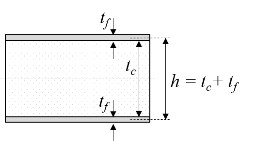
Figure-2: Sandwich, simplified framework
The maximum deflection is a superposition of bending and shear deformation
\begin{equation} \delta = k_b\frac{FL^3}{D_b} + k_s\frac{FL}{S} \tag{5} \end{equation}where $k_b$ is a bending deflection coefficient and $k_s$ is a shear deflection coefficient. For a freely supported beam subjected to a center load, their values are 1/48 and 1/4 respectively. For other cases, tabulated coefficient can be found in for example Sandwich design technology manual from Hexcel or in the DIAB Sandwich Handbook.
The bending stiffness is approximated to
\begin{equation} D_b = \frac{E_f t_f b h^2}{2} \tag{6} \end{equation}while the shear stiffness is
\begin{equation} S = b h G_c \tag{7} \end{equation}where $E_f$ is the effective modulus ($E_x$) of the face sheet laminates and $G_c$ is the shear modulus ($G_{13}$) of the core.
Note that the difference between equation (1) and (6) is minor when the assumptions are fulfilled:
tc = 16.0
tf = 0.5
Ef = m1['E1']
Gc = mcore['G13']
b  = 1
h  = tc+tf

sandw  = [{'mat':m1,    'ori':0, 'thi':  tf},
          {'mat':mcore, 'ori':0, 'thi' : tc},
          {'mat':m1,    'ori':0, 'thi':  tf} ]

Db_eq1 = bendingStiffness(sandw,1)

Db_eq6 = (Ef*tf*b*h**2)/2

print(Db_eq6/Db_eq1)
Example: a freely supported beam subjected to a center load:
kb = 1/48
ks = 1/4
F = 500
L = 250
b = 30
Db = (Ef*tf*b*h**2)/2
S = b*h*Gc

delta_bending = (kb*F*L**3)/Db
delta_shear = ks*F*L/S
delta = delta_bending + delta_shear

print('Deflection = ', delta, 'mm')
print('Contribution from shear deflection is',delta_shear,'mm')
The maximum/minimum stress at the bottom face / top face is
\begin{equation} \sigma = \pm \frac{FL}{4 b h t_f} \tag{8} \end{equation}sigma = (F*L)/(4*b*h*tf)
print('Maximum stress at the mid span is: ',sigma, 'MPa')
For a detailed FEA study of a sandwich beam, se the case study FEA of a sandwich beam


Disclaimer:This site is about polymer composites, designed for educational purposes. Consumption and use of any sort & kind is solely at your own risk.
Fair use: I spent some time making all the pages, and even the figures and illustrations are my own creations. Obviously, you may steal whatever you find useful here, but please show decency and give some acknowledgment if or when copying. Thanks! Contact me: nils.p.vedvik@ntnu.no www.ntnu.edu/employees/nils.p.vedvik
Copyright 2021, All right reserved, I guess.