Parts
Parts are stored in the repository parts and only a constructor such as Part() can add models to the repository:
>>> mdb.Model(name='M1')
>>>
>>> mdb.models['M1'].Part(name='P1')
>>>
According to the Abaqus 2019 documentation, the parameters dimensionality and type are required for Parts(...). However, those seems to have default values:
>>> mdb.models['M1'].parts['P1'].space
THREE_D
>>> mdb.models['M1'].parts['P1'].type
DEFORMABLE_BODY
For compability and consistency reasons, it is probably the best practice to allways include those arguments so the dimensionality and type becomes clear from the code. For instance:
>>>
>>> from abaqusConstants import *
>>>
>>> mdb.models['M1'].Part(name='P2', dimensionality=TWO_D_PLANAR, type=DISCRETE_RIGID_SURFACE)
>>>
>>> mdb.models['M1'].parts['P2'].space
TWO_D_PLANAR
>>>
>>> mdb.models['M1'].parts['P2'].type
DISCRETE_RIGID_SURFACE
Access and iterations
Access to, and iteration over parts, follows the same logic as for other repositories in the model data base. For instance, a model having a number of parts:
>>> mdb.models['Model-1'].parts.keys()
['Part-1', 'Part-2', 'Part-3', 'Part-4']
>>>
>>> prt = mdb.models['Model-1'].parts['Part-1']
>>> type(prt)
<type 'Part'>
>>> prt.name
'Part-1'
>>> prt.type
DEFORMABLE_BODY
>>>
Properties and methods
... the huge set of properties and methods of a part is not suited for listing...:
>>> len(dir(prt))
358
Just the ones starting with 'e':
>>> [i for i in dir(prt) if i[0] in ['e'] ]
['edges', 'editNode', 'elemEdges', 'elemFaces', 'elementEdges', 'elementFaces', 'elements', 'engineeringFeatures']
>>>
Example-1: Brick
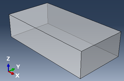
A solid brick was created by extruding a rectangle, where dimensions are 100 by 50 by 25. See Script-1a below.
Script-1a
from abaqus import *
from abaqusConstants import *

def solidBrick(modelname, L, b, h):
    mod = mdb.Model(name=modelname)
    ske = mod.ConstrainedSketch(name='__profile__', sheetSize=200.0)
    ske.rectangle(point1=(0.0, 0.0), point2=(L, b))
    prt = mod.Part(name='Brick', dimensionality=THREE_D, type=DEFORMABLE_BODY)
    prt.BaseSolidExtrude(sketch=ske, depth=h)
    del ske
    prt.DatumCsysByThreePoints(name='Csys1', coordSysType=CARTESIAN)
    session.viewports['Viewport: 1'].setValues(displayedObject=prt)

solidBrick(modelname='M1', L=100.0, b=50.0, h=25.0)
Properties and methods to explore:
part.cells               part.faces.getBoundingBox()
part.faces               part.vertices.getBoundingBox()
part.edges               part.vertices[i].getEdges()
part.vertices            part.faces[i].getSize()
Accessing the part:
>>> prt = mdb.models['M1'].parts['Brick']Without much effort, we can manually estimate that the brick has 1 cell (volume), 6 faces, 12 edges and 8 vertices (points). These are stored in different sequences. Counting everything:
>>> print len(prt.cells), len(prt.faces), len(prt.edges), len(prt.vertices)
1 6 12 8
The knowledge of the specific type of a sequence will become important later on:
>>> print type(prt.cells), type(prt.faces), type(prt.edges), type(prt.vertices)
<type 'CellArray'> <type 'FaceArray'> <type 'EdgeArray'> <type 'VertexArray'>
For instance, faces has six objects:
>>> print prt.faces
['Face object', 'Face object', 'Face object', 'Face object', 'Face object', 'Face object']
and its own methods (private methods removed from the list):
>>> dir(prt.faces)
['findAt', 'getBoundingBox', 'getByBoundingBox', 'getByBoundingCylinder', 'getByBoundingSphere',
 'getClosest', 'getExteriorEdges', 'getMask', 'getSequenceFromMask', 'index', 'pointsOn']
For example, the method getBoundingBox() returns a dictionary with two items; 'high' and 'low', representing the extent of coordinates across all faces:
>>> prt.faces.getBoundingBox()
{'high': (100.0, 50.0, 25.0), 'low': (0.0, 0.0, 0.0)}
A similar method exists for vertices, and with the same result as expected:
>>> prt.vertices.getBoundingBox()
{'high': (100.0, 50.0, 25.0), 'low': (0.0, 0.0, 0.0)}
Properties of a vertice:
>>> print prt.vertices[0]
({'featureName': 'Solid extrude-1', 'index': 0, 'instanceName': None, 'isReferenceRep': False,
  'pointOn': ((0.0, 0.0, 25.0),)})
A vertice object has methods as well:
>>>dir(prt.vertices[0])
['featureName', 'getEdges', 'getElements', 'getNodes', 'index', 'instanceName', 'isReferenceRep', 'pointOn']
For instance, get the edges connected to the first vertice in the sequence:
>>> some_edges = prt.vertices[0].getEdges()
>>> print some_edges
(0, 3, 10)
As indicated, getEdges() returns a tuple of indices, not a sequence of edge objects. A sequence can however be made by
edgesA = prt.edges[0:1] + prt.edges[3:4] + prt.edges[10:11]Or more generic:
>>> edgesB = prt.edges[0:0] # an empty sequence
>>> inds = prt.vertices[0].getEdges()
>>> for i in inds:
...     edgesB = edgesB + prt.edges[i:i+1]
>>> print edgesB
['Edge object', 'Edge object', 'Edge object']
>>> [e.index for e in edgesB]
[0, 3, 10]
Sample problem
Create a script that assumes no prior knowledg of a part but the name of the model and part. The script shall report:
- the number of all geometrical enteties
- the area of individual faces in a list sortbed by size, as well as the total area
- volume and centroid coordinates of cells
- dimensions according to the extent of vertices
- the maximum and minimum length of edges
- the greatest distance between two vertices
Access to the part
prt = mdb.models[modelname].parts[partname]Relevant methods
prt.faces[i].getSize(printResults=OFF)                # area of a face
prt.getVolume(cells)                                  # volum of cells
prt.getCentroid(cells)                                # centroid coordinate of cells
prt.vertices.getBoundingBox()                         # min and max coordinate values
prt.edge[i].getSize(printResults=OFF)                 # length of an edge
prt.getDistance(entity1,entity2,printResults=OFF)     # distance between two entities
Final result: Script-1b
Script-1b
from abaqus import *
from abaqusConstants import *

def partProperties(modelname, partname):
    prt = mdb.models[modelname].parts[partname]

    # Number of geometrical enteties:
    itms = [prt.cells, prt.faces, prt.edges, prt.vertices]
    print 'Number of cells, faces, edges, vertices:', [len(i) for i in itms]

    # Areas of faces and total area:
    areaList = [float(f.getSize(printResults=OFF)) for f in prt.faces]
    areaList.sort()
    print 'Area of faces, sorted:', areaList
    print 'Total area is', sum(areaList)

    # Volume and centroid of all cells:
    totVol = prt.getVolume(cells= prt.cells)
    print 'Total volume:', totVol
    centroid = prt.getCentroid(cells=prt.cells)
    print 'Centroid coordinates:', centroid

    # Dimensions, according to vertices:
    extr = prt.vertices.getBoundingBox()
    print 'Min coordinates, vertices:', extr['low']
    print 'Max coordinates, vertices:', extr['high']
    import numpy as np
    high, low = np.array(extr['high']), np.array(extr['low'])
    dims = high-low
    print 'Dimensions according to vertices, (L, b, h):', dims

    # Finding the maximum and minimum length of edges:
    lengths = [edge.getSize(printResults=OFF) for edge in prt.edges]
    print 'Max length of edges:', max(lengths)
    print 'Min length of edges:', min(lengths)

    # Greatest distance between two vertices:
    d=[prt.getDistance(entity1=e1,entity2=e2,printResults=OFF) for e1 in prt.edges for e2 in prt.edges]
    print 'Greatest distance between vertices:', max(d)

partProperties(modelname='M1', partname='Brick')
Script-2a
from abaqus import *
from abaqusConstants import *
def plateWithHole(modelname, L, b, h, r, cx, cy):
mod = mdb.Model(name=modelname)
ske = mod.ConstrainedSketch(name='__profile__', sheetSize=200.0)
ske.rectangle(point1=(0.0, 0.0), point2=(L, b))
ske.CircleByCenterPerimeter(center=(cx, cy), point1=(cx+r, cy))
prt = mod.Part(name='P1', dimensionality=THREE_D, type=DEFORMABLE_BODY)
prt.BaseSolidExtrude(sketch=ske, depth=h)
del ske
session.viewports['Viewport: 1'].setValues(displayedObject=prt)
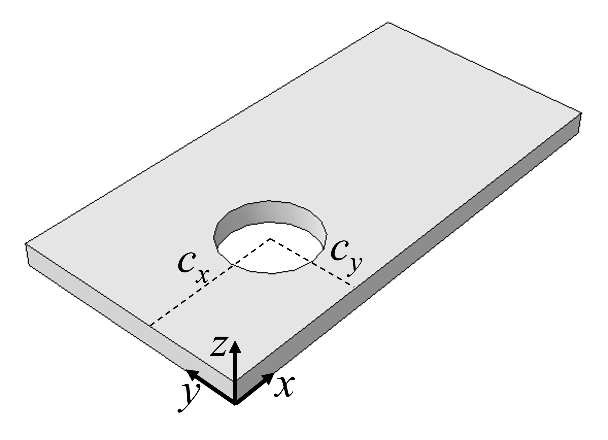
plateWithHole(modelname='M1', L=100.0, b=50.0, h=5.0, r=10.0, cx=30.0, cy=20.0)
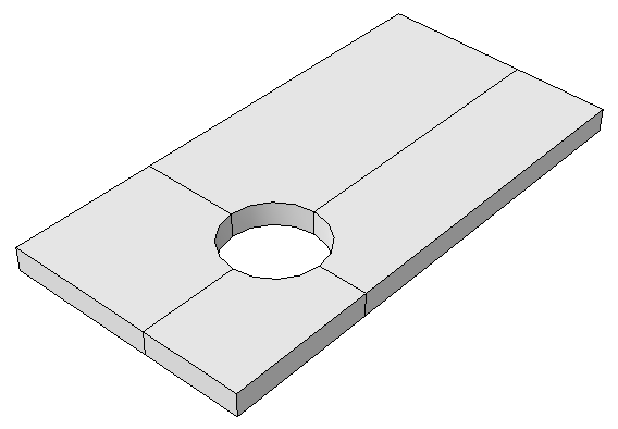
The task from this point on is to create partitions as illustrated in the figure to the right. There are several methods available for this task, some of them to be demonstrated:
PartitionCellByDatumPlane(cells, datumePlane)
Datum planes are obviously needed, and the easiest method is to offset principal planes y-z and x-z by cx and cy respectively:
>>> cx, cy = 30.0, 20.0
>>> prt = mdb.models['M1'].parts['P1']
>>> plane1 = prt.DatumPlaneByPrincipalPlane(principalPlane=YZPLANE, offset=cx)
>>> plane2 = prt.DatumPlaneByPrincipalPlane(principalPlane=XZPLANE, offset=cy)
However, the method DatumPlaneByPrincipalPlane(...) does not return a datum plane as we may have anticipated, but rather a feature:
>>> type(plane1)
<type 'Feature'>
Hence, there is a repository for features
>>> type(prt.features)
<type 'Repository'>
and other features in the reposity of the part can be listed:
>>> print prt.features
{'Solid extrude-1': 'Feature object', 'Datum plane-1': 'Feature object', 'Datum plane-2': 'Feature object'}
>>> or
A feature object has an id,
>>> print prt.features['Datum plane-1']
({'children': '', 'id': 2, 'isOutOfDate': False, 'name': 'Datum plane-1', 'offset': 30.0, 'parents': '',
  'path': 'unknown', 'sketch': 'unknown'})
and this id is the key for the datum plane in the repository datums:
>>> print prt.datums
{2: 'DatumPlane object', 3: 'DatumPlane object'}
>>> type(prt.datums[2])
<type 'DatumPlane'>
>>> print prt.datums[2]
({'normal': (1.0, 0.0, 0.0), 'pointOn': (30.0, 0.0, 0.0)})
Hence, the two datume planes can be referenced by
>>> id1 = plane1.id
>>> id2 = plane2.id
>>> dp1 = prt.datums[id1]
>>> dp2 = prt.datums[id2]
The complete code following the existing code in Script-2a is therefore
    plane1 = prt.DatumPlaneByPrincipalPlane(principalPlane=YZPLANE, offset=cx)
    plane2 = prt.DatumPlaneByPrincipalPlane(principalPlane=XZPLANE, offset=cy)
    id1 = plane1.id
    id2 = plane2.id
    dp1 = prt.datums[id1]
    dp2 = prt.datums[id2]
    prt.PartitionCellByDatumPlane(cells=prt.cells, datumPlane=dp1)
    prt.PartitionCellByDatumPlane(cells=prt.cells, datumPlane=dp2)
or in a more compact format as in the following result:
Script-2b
from abaqus import *
from abaqusConstants import *

def plateWithHole(modelname, L, b, h, r, cx, cy):
    mod = mdb.Model(name=modelname)
    ske = mod.ConstrainedSketch(name='__profile__', sheetSize=200.0)
    ske.rectangle(point1=(0.0, 0.0), point2=(L, b))
    ske.CircleByCenterPerimeter(center=(cx, cy), point1=(cx+r, cy))
    prt = mod.Part(name='P1', dimensionality=THREE_D, type=DEFORMABLE_BODY)
    prt.BaseSolidExtrude(sketch=ske, depth=h)
    del ske
    session.viewports['Viewport: 1'].setValues(displayedObject=prt)

    # Partitions, Alternative 1

    id1 = prt.DatumPlaneByPrincipalPlane(principalPlane=YZPLANE, offset=cx).id
    id2 = prt.DatumPlaneByPrincipalPlane(principalPlane=XZPLANE, offset=cy).id
    prt.PartitionCellByDatumPlane(cells=prt.cells, datumPlane=prt.datums[id1])
    prt.PartitionCellByDatumPlane(cells=prt.cells, datumPlane=prt.datums[id2])

plateWithHole(modelname='M1', L=100.0, b=50.0, h=5.0, r=10.0, cx=30.0, cy=20.0)
PartitionCellByPlanePointNormal(cells, point, normal)
The previous method required just a datum plane, while this method requires a point and a normal. The point can be a Vertex, DatumPoint or InterestingPoint, while the normal is a straight Edge or DatumAxis.
Create a datum point at the center of the hole and return the id of it:
idp = prt.DatumPointByCoordinate( coords=(cx,cy,0)).idThen, normals are required. The following method is rather straight forward:
    normal1 = prt.edges.findAt( coordinates=((L/2.0, 0, 0),))[0]
    prt.PartitionCellByPlanePointNormal(cells=prt.cells, point=prt.datums[idp], normal=normal1)
    normal2 = prt.edges.findAt( coordinates=((0, b/2.0, 0),))[0]
    prt.PartitionCellByPlanePointNormal(cells=prt.cells, point=prt.datums[idp], normal=normal2)
Note that findAt(...) returns an EdgeArray. However, there is only one edge (if the logic of selection holds), and therefore we can pick the first edge in the array: findAt(...)[0].
Script-2c
from abaqus import *
from abaqusConstants import *

def plateWithHole(modelname, L, b, h, r, cx, cy):
    mod = mdb.Model(name=modelname)
    ske = mod.ConstrainedSketch(name='__profile__', sheetSize=200.0)
    ske.rectangle(point1=(0.0, 0.0), point2=(L, b))
    ske.CircleByCenterPerimeter(center=(cx, cy), point1=(cx+r, cy))
    prt = mod.Part(name='P1', dimensionality=THREE_D, type=DEFORMABLE_BODY)
    prt.BaseSolidExtrude(sketch=ske, depth=h)
    del ske
    session.viewports['Viewport: 1'].setValues(displayedObject=prt)

    # Partitions, Alternative 2

    idp = prt.DatumPointByCoordinate( coords=(cx,cy,0)).id
    normal1 = prt.edges.findAt( coordinates=((L/2.0, 0, 0),))[0]
    prt.PartitionCellByPlanePointNormal(cells=prt.cells, point=prt.datums[idp], normal=normal1)
    normal2 = prt.edges.findAt( coordinates=((0, b/2.0, 0),))[0]
    prt.PartitionCellByPlanePointNormal(cells=prt.cells, point=prt.datums[idp], normal=normal2)

plateWithHole(modelname='M1', L=100.0, b=50.0, h=5.0, r=10.0, cx=30.0, cy=20.0)
PartitionCellByPlaneThreePoints(cells, point1, point2, point3)
Some methods of partitioning are very simple when using the GUI, while being rather involved for coding. That should, however, not prevent us from trying...
For instance, the code generated in abaqus.rpy for the session in the recording to the right is:
p = mdb.models['M1'].parts['P1']
c = p.cells
pickedCells = c.getSequenceFromMask(mask=('[#1 ]',),)
v1, e1, d1 = p.vertices, p.edges, p.datums
p.PartitionCellByPlaneThreePoints(point2=v1[9],
    point3=v1[8], cells=pickedCells,
    point1=p.InterestingPoint(edge=e1[13], rule=CENTER))
Translated to the variables used in prior scripts, removing assignments not needed and re-arranging the arguments and breaking down to something readable...
pt1 = prt.InterestingPoint(edge=prt.edges[13], rule=CENTER)
pt2 = prt.vertices[9]
pt3 = prt.vertices[8]
prt.PartitionCellByPlaneThreePoints(cells=prt.cells, point1=pt1, point2=pt2, point3=pt3)
The task is now to figure out a way to select the edge and the two vertices using some methods and logic based on geometrical features. A working solution is for example the use of getByBoundingCylinder(...) and getByBoundingSphere(...):
    edge = prt.edges.getByBoundingCylinder(center1=(cx, cy, -0.001), center2=(cx, cy, 0.001), radius=r+0.001)[0]
    vertice1 = prt.vertices.getByBoundingSphere(center=(cx+r, cy, 0), radius = 0.001)[0]
    vertice2 = prt.vertices.getByBoundingSphere(center=(cx+r, cy, h), radius = 0.001)[0]
    pt1 = prt.InterestingPoint(edge=edge, rule=CENTER)
    pt2 = vertice1
    pt3 = vertice2
    prt.PartitionCellByPlaneThreePoints(cells=prt.cells, point1=pt1, point2=pt2, point3=pt3)
Now that one partition has been made, the set of edges and vertices has changed. Hence, a new round with proper logic and selection must be written.
Partly result is found in Script-2d.
Script-2d
from abaqus import *
from abaqusConstants import *

def plateWithHole(modelname, L, b, h, r, cx, cy):
    mod = mdb.Model(name=modelname)
    ske = mod.ConstrainedSketch(name='__profile__', sheetSize=200.0)
    ske.rectangle(point1=(0.0, 0.0), point2=(L, b))
    ske.CircleByCenterPerimeter(center=(cx, cy), point1=(cx+r, cy))
    prt = mod.Part(name='P1', dimensionality=THREE_D, type=DEFORMABLE_BODY)
    prt.BaseSolidExtrude(sketch=ske, depth=h)
    del ske
    session.viewports['Viewport: 1'].setValues(displayedObject=prt)

    # Partitions, Alternative 3

    # - first partition:
    edge = prt.edges.getByBoundingCylinder(center1=(cx, cy, -0.001), center2=(cx, cy, 0.001), radius=r+0.001)[0]
    vertice1 = prt.vertices.getByBoundingSphere(center=(cx+r, cy, 0), radius = 0.001)[0]
    vertice2 = prt.vertices.getByBoundingSphere(center=(cx+r, cy, h), radius = 0.001)[0]
    pt1 = prt.InterestingPoint(edge=edge, rule=CENTER)
    pt2 = vertice1
    pt3 = vertice2
    prt.PartitionCellByPlaneThreePoints(cells=prt.cells, point1=pt1, point2=pt2, point3=pt3)
    # - second partition:
    # Too much hazle..

plateWithHole(modelname='M1', L=100.0, b=50.0, h=5.0, r=10.0, cx=30.0, cy=20.0)


