Elements
Solid 3D elements
Three-dimensional solid elements for structural analysis include:
- Tetrahedron (Tet), 4 nodes linear interpolation and 10 nodes quadratic interpolation
- Triangular prism (Wedge), 6 nodes linear interpolation or 15 nodes quadratic interpolation
Brick (Hex), 8 nodes linear interpolation or 20 nodes quadratic interpolation
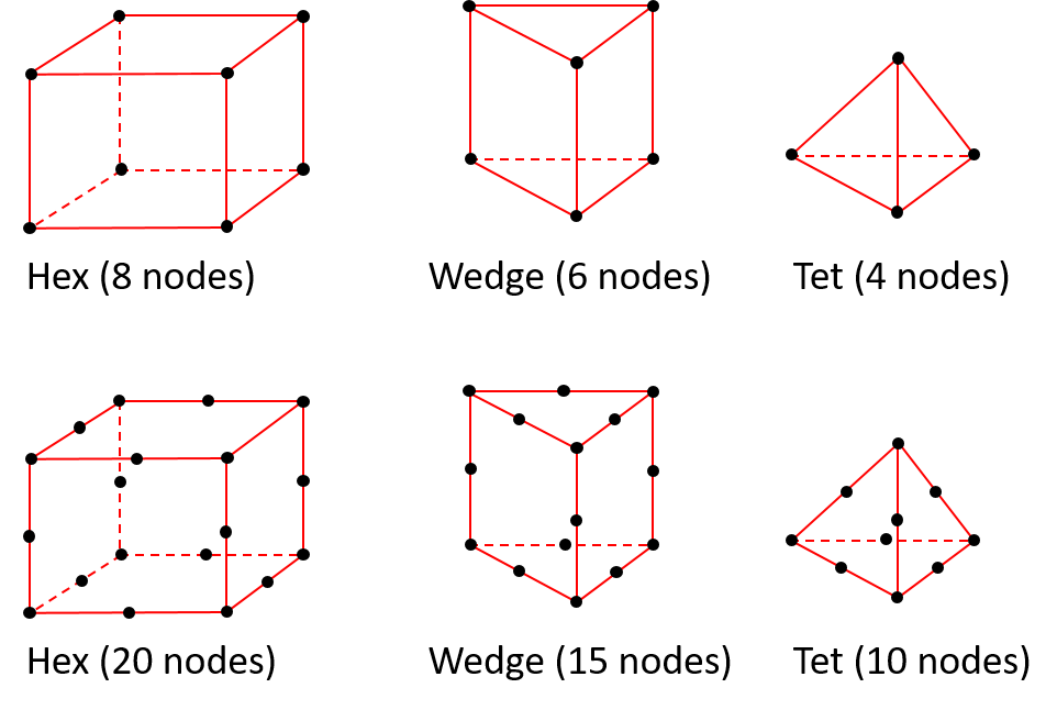
Figure-1: Solid elements
The various elements comes with several options such as full or reduced integration, incompatible mode and hourglass control.
Figure-2: Hex meshing
Abaqus elements
A detailed description and discussion on solid 3D elements can be found in the Abaqus Documentation. The most relevant issues are emphasized below:
General recommendations:
- Make all elements as well shaped as possible to improve convergence and accuracy.
- If possible, use hexahedral elements with reduced integration such as C3D8R and C3D20 in three-dimensional analyses since they give the best results for the minimum cost.
- Tetrahedral elements are geometrically versatile in automatic meshing algorithms and enable mesh on complex shapes. First-order tetrahedral elements such as C3D4 are usually overly stiff (see Figure-3) and should be avoided as much as possible. For tetrahedral element meshes the second-order tetrahedral elements such as C3D10, should be used.
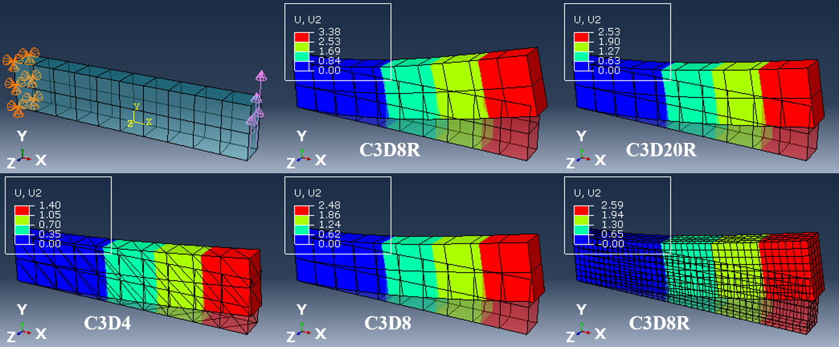
Figure-3: Performance of solid elements when subjected to predominantly bending. The most accurate
results are obtained by C3D20R elements or a sufficient number of C3D8R elements.
- The linear version of the wedge element C3D6 should generally be used only when necessary to complete a mesh, and, even then, the element should be far from any areas where accurate results are needed.
- Hourglassing can be a problem with first-order, reduced-integration elements like C3D8R, see Figure-4. Since the elements have only one integration point, it is possible for them to distort in such a way that the strains calculated at the integration point are all zero, which, in turn, leads to uncontrolled distortion of the mesh. First-order, reduced-integration elements in Abaqus include hourglass control, but they should be used with reasonably fine meshes.
- First-order, reduced-integration elements like C3D8R have virtually no bending stiffness for the reasons given above, and sections subjected to bending should have at least two elements through the thickness. Typically, more than 4 elements through the section of flexural members are required for reasonable accuracy, see Figure 3.
- Fully integrated elements may suffer from shear and volumetric locking. Shear locking occurs in first-order, fully integrated elements (like C3D8) that are subjected to bending. The numerical formulation of the elements gives rise to shear strains that do not really exist—the so-called parasitic shear. Therefore, these elements may behave too stiff in bending modes.
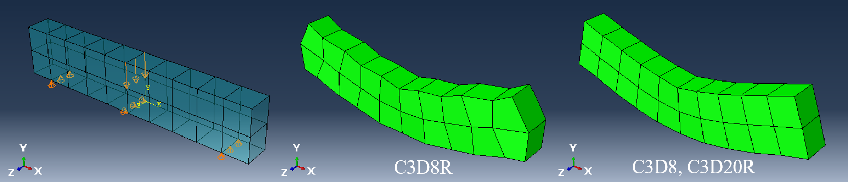
Figure-4: Example of hourglassing for element type C3D8R compared to C3D8 or C3D20R subjected to concentrated loads
Elements for composites and layered solid structures
For most of the examples and problems in the course, we will be using one of two solid 3D elements:
- C3D8R: 8-node linear brick (Hex), reduced integration with hourglass control
- C3D20R: 20-node quadratic brick (Hex), reduced integration
Conventional shell elements
Shell elements are used to model structures in which the thickness is significantly smaller than the other dimensions. Conventional shell elements use this condition to discretize a body by defining the geometry at a reference surface. In this case the thickness is defined through the section property definition. The nodes in conventional shell elements have both displacement and rotational degrees of freedom.
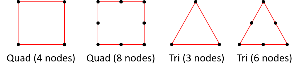
Figure-5: Shell elements
Abaqus elements
A detailed description and discussion on solid 3D elements can be found in the Abaqus Documentation. The most relevant issues are emphasized below:
General recommendations:
- Make all elements as well shaped as possible to improve convergence and accuracy.
- S4R is a 4-node general-purpose shell with reduced integration, hourglass control and finite membrane strains. It is the default choice and suitable for most problems. The element can be combined with S3, but the number of TRI elements should be minimized.
- S3 is a 3-node triangular general-purpose shell with finite membrane strains. The element should be used only when necessary to complete a mesh in combination with S4R or S4 since it may exhibit overly stiff response in membrane deformation.
- S4 is a fully integrated, general-purpose, finite-membrane-strain shell element. The element's membrane response is treated with an assumed strain formulation that gives accurate solutions to in-plane bending problems, is not sensitive to element distortion, and avoids parasitic locking. The element has four integration locations per element compared with one integration location for S4R, which makes the element computationally more expensive. S4 is compatible with both S4R and S3R. S4 can be used for problems prone to membrane- or bending-mode hourglassing, in areas where greater solution accuracy is required, or for problems where in-plane bending is expected. In all of these situations S4 will outperform element type S4R.
- The combination of S8R and STRI65 can be a good solution on structures where it is not possible to create mesh without a significant number of triangular shell elements. This solution comes, however, with a high computational cost.
Note: All shell elements mentioned above include methods for estimating the contribution of transverse shear strain to the out-of-plane deformation.


