Layered structures
Discrete solid layers
For structures where the local 3-dimensional stress are important or otherwise in the scope of the finite element analyses, individual layers are typically being modeled as discrete solid regions. Examples include edge effects, detailed loading conditions at joints and connections and assessment and simulation of interlaminar stresses and failure.
These models will typically have at least on solid element through the thickness of each layer. The connection between the layers can range from simple nodal connections (sharing of nodes) to cohesive techniques including cohesive surfaces and cohesive elements between the layers.
Models with discrete solid layers will obviously involve a huge number of elements for even very small areas of a laminated structure, and this type of abstraction is generally limited to localized effects.
Relevant case studies
Examples from Abaqus Scripting
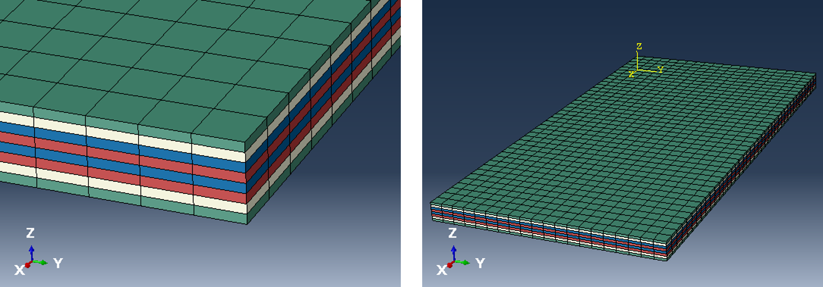
Figure-1: Discrete layers of solid elements.
Solid composite layup
A Composite Layup in Abaqus CAE is just an alias for a section property derived from a layered structure (i.e. a laminate). A Solid composite layup is applicable for solid Hex elements such as C3D8R and C3D20R. This modeling technique is useful when through-the-thickness stresses are important while discretization for interlaminar effects such as delamination are not within the scope of the problem.
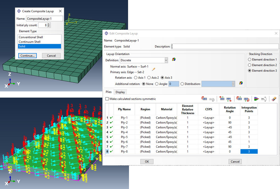
Figure-2: Solid composite layup.
Important considerations:
- The thickness of the layers are relative to the element thickness. Hence, if all layers are included in the composite layup, this layup will be repeated for all the elements through the thickness. For most of the cases, this technique makes sense only for a mesh with only one element through the thickness.
- First-order, reduced-integration elements like C3D8R can generally not be used for structures having only one element through the thickness since they are unable to represent the stiffness in a bending mode. The element C3D20 is typically the preferred choice.
- The stack direction must be specified explicitly.
- If specified in field output request, detailed results are available for the individual layers.
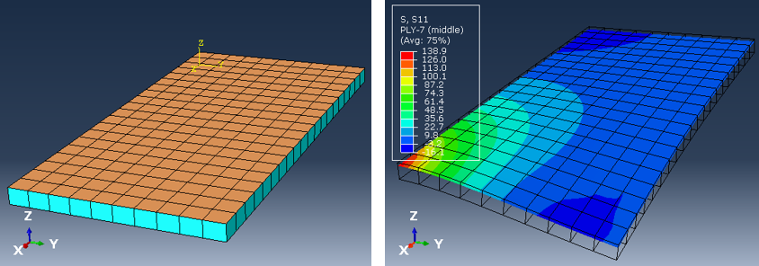
Figure-3: Stack direction and results for individual layers.
Conventional shell composite layup
Shell elements are used to model structures in which the thickness is significantly smaller than the other dimensions. Conventional shell elements use this condition to discretize a body by defining the geometry at a reference surface. In this case the thickness is defined through the section property definition, and for a layered structure, the section in a composite layup for conventional shell elements.
Since shell modeling assume approximate plane stress conditions, this method may not be able to capture localized effects where a 3-dimensional stress state is present. Nevertheless, this type of modelling abstraction is very efficient and remain as the dominating approach for design and engineering of thin shell composite structures.
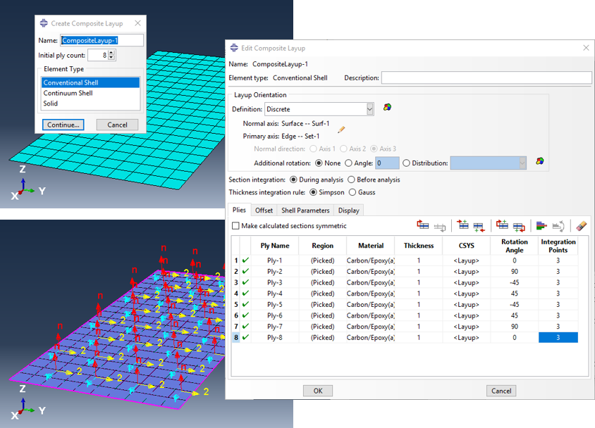
Figure-4: Conventional shell composite section.
Relevant case studies
- Todo
Examples from Abaqus Scripting


