Arrays of holes
A rectangular plate with dimensions X by Y is a part of a mechanical system interacting with some fluid and thermal conditions that requires many holes. The number of holes and the diameter d of those are currently unknown and therefore a subject for optimization by simulations.
There shall be some sealing along the edges, requiring an edge distance ed. For structural reasons, the distance between holes must be grater than a given value, i.e. >dist.
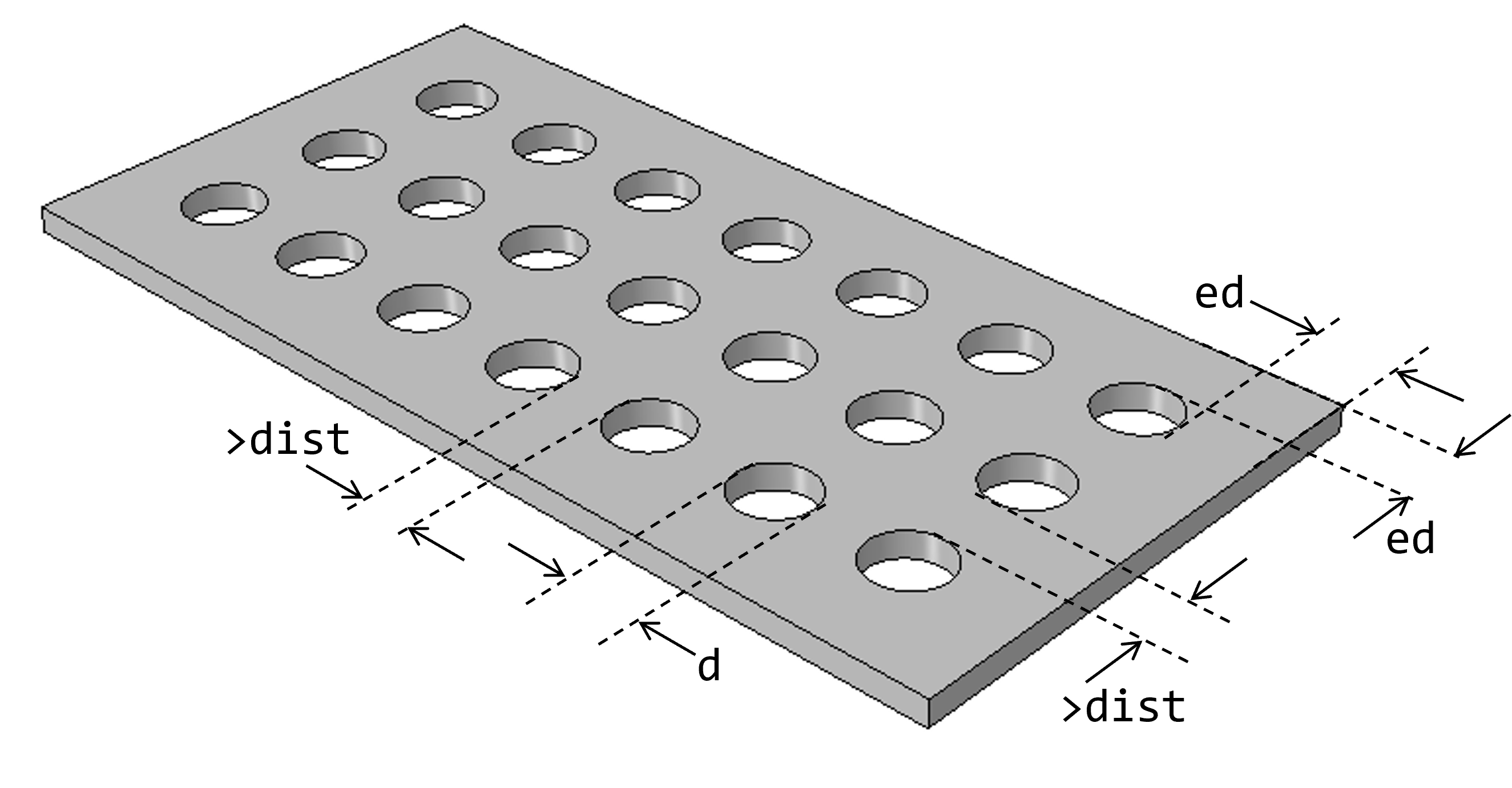
The total lengt is
X = 2*ed + nx*d + (nx-1)*distwhere nx is the number of holes along the x-direction.
The number of holes along the x-direction can be solved from the previous expression. It must be an integer, rounded down:
nx = int( (X - 2*ed + dist)/(d + dist) )Correspondingly, the number of holes along the y-direction is
ny = int( (Y - 2*ed + dist)/(d + dist) )Putting everything into a function that computes the x-y coordinates of the holes and uses matplotlib for illustration:
import matplotlib.pyplot as plt

def arrayOfHoles(X, Y, d, ed, dist):
    nx = int(  (X-2*ed+dist)/(d+dist)  )      # number of holes along x
    ny = int(  (Y-2*ed+dist)/(d+dist)  )      # number of holes along y
    dX = (X-2*ed-d)/(nx-1)                    # center distance between holes along x
    dY = (Y-2*ed-d)/(ny-1)                    # center distance between holes along y
    xs = [ed+d/2+i*dX for i in range(0,nx)]   # center x-coordinates of holes
    ys = [ed+d/2+i*dY for i in range(0,ny)]   # center y-coordinates of holes
    # Illustration
    fig,ax=plt.subplots(figsize=(3,3))
    ax.set_axis_off()
    ax.set_aspect('equal', adjustable='box')
    ax.plot((0,X,X,0,0),(0,0,Y,Y,0), color='black')
    for x in xs:
        for y in ys:
            circle = plt.Circle((x,y),d/2, color='black', fc='white')
            ax.add_artist(circle)
    plt.show()
arrayOfHoles(X=200, Y=100, d=20, ed=15, dist = 10)
arrayOfHoles(X=200, Y=100, d=15, ed=15, dist =  5)
arrayOfHoles(X=200, Y=100, d=10, ed=15, dist =  5)


Abaqus implementation
from abaqus import *
from abaqusConstants import *

def pwh(modelname,X, Y, d, ed, dist, t):

    nx = int(  (X-2*ed+dist)/(d+dist)  )
    ny = int(  (Y-2*ed+dist)/(d+dist)  )
    dX = (X-2.0*ed-d)/(nx-1)
    dY = (Y-2.0*ed-d)/(ny-1)
    xs = [ed+d/2.0+i*dX for i in range(0,nx)]
    ys = [ed+d/2.0+i*dY for i in range(0,ny)]

    mod = mdb.Model(name=modelname)
    ske = mod.ConstrainedSketch(name='__profile__', sheetSize=200.0)
    ske.rectangle(point1=(0.0, 0.0), point2=(X, Y))
    for x in xs:
        for y in ys:
            ske.CircleByCenterPerimeter(center=(x, y), point1=(x, y+d/2.0))
    prt = mod.Part(name='Plate', dimensionality=THREE_D, type=DEFORMABLE_BODY)
    prt.BaseSolidExtrude(sketch=ske, depth=t)
    del mod.sketches['__profile__']
    session.viewports['Viewport: 1'].setValues(displayedObject=prt)

pwh(modelname='M1', X=200.0, Y=100.0, d=15.0, ed=15.0, dist = 10.0, t=5.0)
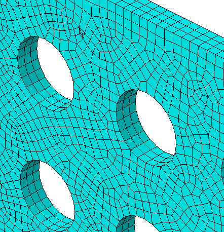
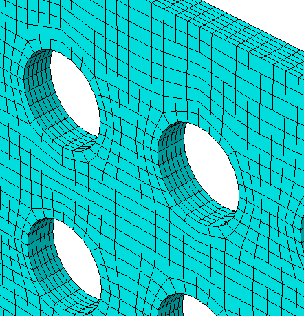
Partitions and mesh
A mesh can be created on the part as is without too much quality issues regarding the element shape. However, higher quality with the same number of elements, of fewer, can be achived by partitioning.
A simple technique is the one using planes:
- through the center of every holes, and
- mid-way between the holes.
The coordinates of the holes are directly available from the parameters xs and ys.
Then, finding the positions between the holes using simple logic:
    # Partitions

    for x in xs:
        id=prt.DatumPlaneByPrincipalPlane(principalPlane=YZPLANE, offset=x).id
        prt.PartitionCellByDatumPlane(datumPlane=prt.datums[id], cells=prt.cells)
    for y in ys:
        id=prt.DatumPlaneByPrincipalPlane(principalPlane=XZPLANE, offset=y).id
        prt.PartitionCellByDatumPlane(datumPlane=prt.datums[id], cells=prt.cells)
    for x in [(xs[i]+xs[i+1])/2.0 for i in range(0, len(xs)-1)]:
        id=prt.DatumPlaneByPrincipalPlane(principalPlane=YZPLANE, offset=x).id
        prt.PartitionCellByDatumPlane(datumPlane=prt.datums[id], cells=prt.cells)
    for y in [(ys[i]+ys[i+1])/2.0 for i in range(0, len(ys)-1)]:
        id=prt.DatumPlaneByPrincipalPlane(principalPlane=XZPLANE, offset=y).id
        prt.PartitionCellByDatumPlane(datumPlane=prt.datums[id], cells=prt.cells)
Mesh control requires identification of edges: The number of elements nelt through the thickness shall be an arguement in the function:
    # Sets (required for meshing)

    set1 = prt.Set(name='edges all', edges=prt.edges)
    edgb = prt.edges.getByBoundingBox(zMax=0)
    edgt = prt.edges.getByBoundingBox(zMin=t)
    set2 = prt.Set(name='edges bot top', edges=edgb+edgt)
    set3 = prt.SetByBoolean(name='edges thickness', sets=(set1,set2), operation=DIFFERENCE)

    # Mesh

    prt.seedPart(size=esize, deviationFactor=0.1, minSizeFactor=0.1)
    prt.seedEdgeByNumber(edges=set3.edges, number=nelt, constraint=FINER)
    prt.generateMesh()
The rest of the script is of no particular interest, just given as an example:
from abaqus import *
from abaqusConstants import *
from customtools import getByPO, getByR

def pwh(modelname,X, Y, d, ed, dist, t, esize, nelt, P):

    nx = int(  (X-2*ed+dist)/(d+dist)  )
    ny = int(  (Y-2*ed+dist)/(d+dist)  )
    dX = (X-2.0*ed-d)/(nx-1)
    dY = (Y-2.0*ed-d)/(ny-1)
    xs = [ed+d/2.0+i*dX for i in range(0,nx)]
    ys = [ed+d/2.0+i*dY for i in range(0,ny)]

    mod = mdb.Model(name=modelname)
    ske = mod.ConstrainedSketch(name='__profile__', sheetSize=200.0)
    ske.rectangle(point1=(0.0, 0.0), point2=(X, Y))
    for x in xs:
        for y in ys:
            ske.CircleByCenterPerimeter(center=(x, y), point1=(x, y+d/2.0))
    prt = mod.Part(name='Plate', dimensionality=THREE_D, type=DEFORMABLE_BODY)
    prt.BaseSolidExtrude(sketch=ske, depth=t)
    del mod.sketches['__profile__']
    session.viewports['Viewport: 1'].setValues(displayedObject=prt)

    # Partitions

    for x in xs:
        id=prt.DatumPlaneByPrincipalPlane(principalPlane=YZPLANE, offset=x).id
        prt.PartitionCellByDatumPlane(datumPlane=prt.datums[id], cells=prt.cells)
    for y in ys:
        id=prt.DatumPlaneByPrincipalPlane(principalPlane=XZPLANE, offset=y).id
        prt.PartitionCellByDatumPlane(datumPlane=prt.datums[id], cells=prt.cells)
    for x in [(xs[i]+xs[i+1])/2.0 for i in range(0, len(xs)-1)]:
        id=prt.DatumPlaneByPrincipalPlane(principalPlane=YZPLANE, offset=x).id
        prt.PartitionCellByDatumPlane(datumPlane=prt.datums[id], cells=prt.cells)
    for y in [(ys[i]+ys[i+1])/2.0 for i in range(0, len(ys)-1)]:
        id=prt.DatumPlaneByPrincipalPlane(principalPlane=XZPLANE, offset=y).id
        prt.PartitionCellByDatumPlane(datumPlane=prt.datums[id], cells=prt.cells)

    # Sets (required for meshing)

    set1 = prt.Set(name='edges all', edges=prt.edges)
    edgb = prt.edges.getByBoundingBox(zMax=0)
    edgt = prt.edges.getByBoundingBox(zMin=t)
    set2 = prt.Set(name='edges bot top', edges=edgb+edgt)
    set3 = prt.SetByBoolean(name='edges thickness', sets=(set1,set2), operation=DIFFERENCE)

    # Mesh

    prt.seedPart(size=esize, deviationFactor=0.1, minSizeFactor=0.1)
    prt.seedEdgeByNumber(edges=set3.edges, number=nelt, constraint=FINER)
    prt.generateMesh()

    # Properties

    mat = mod.Material(name='Aluminum Generic')
    mat.Density(table=((2700E-12, ), ))
    mat.Elastic(table=((70000.0, 0.34), ))
    mat.Expansion(table=((23.0E-06, ), ))
    mod.HomogeneousSolidSection(name='Sec1', material='Aluminum Generic')
    region = prt.Set(name='cells-all', cells=prt.cells)
    prt.SectionAssignment(region=region, sectionName='Sec1')

    # Assembly

    ass = mod.rootAssembly
    ass.DatumCsysByDefault(CARTESIAN)
    ins = ass.Instance(name='Plate', part=prt, dependent=ON)

    # Step, loading and job

    mod.StaticStep(name='Step-1', previous='Initial')
    edgs = getByPO(ins.edges, x=0, z=0) + getByPO(ins.edges, x=X, z=0)
    region = ass.Set(name='edges z-support', edges=edgs)
    mod.DisplacementBC(name='z-support', createStepName='Step-1', region=region, u3=0.0)
    verts1 = ins.vertices.findAt(coordinates=((0,0,0),(0,Y,0)))
    region = ass.Set(name='vertices ux=0', vertices=verts1)
    mod.DisplacementBC(name='ux=0', createStepName='Step-1', region=region, u1=0.0)
    verts2 = ins.vertices.findAt(coordinates=((0,0,0),))
    region = ass.Set(name='vertices uy=0', vertices=verts2)
    mod.DisplacementBC(name='uy=0', createStepName='Step-1', region=region, u2=0.0)
    side1Faces1 = getByPO(ins.faces, z=t)
    region = ass.Surface(name='surf top', side1Faces=getByPO(ins.faces, z=t))
    mod.Pressure(name='P-top', createStepName='Step-1', region=region, magnitude=P, )
    session.viewports['Viewport: 1'].assemblyDisplay.setValues(mesh=OFF)

    mdb.Job(name=modelname, model=modelname)


pwh(modelname='M1', X=200.0, Y=100.0, d=15.0, ed=15.0, dist = 10.0, t=5.0, esize=2, nelt=6, P=1)


