I-profiles
I-beams are much used structural elements and they therefore deserve some attention....
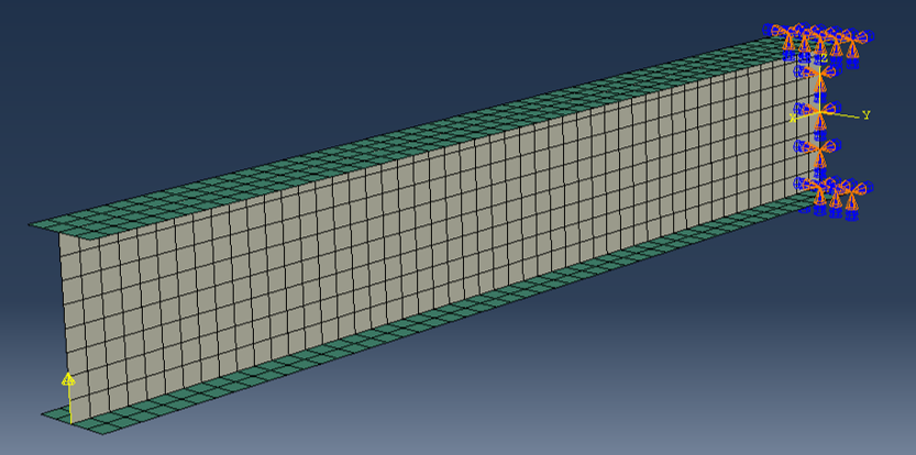
Model-1: Basic shell model
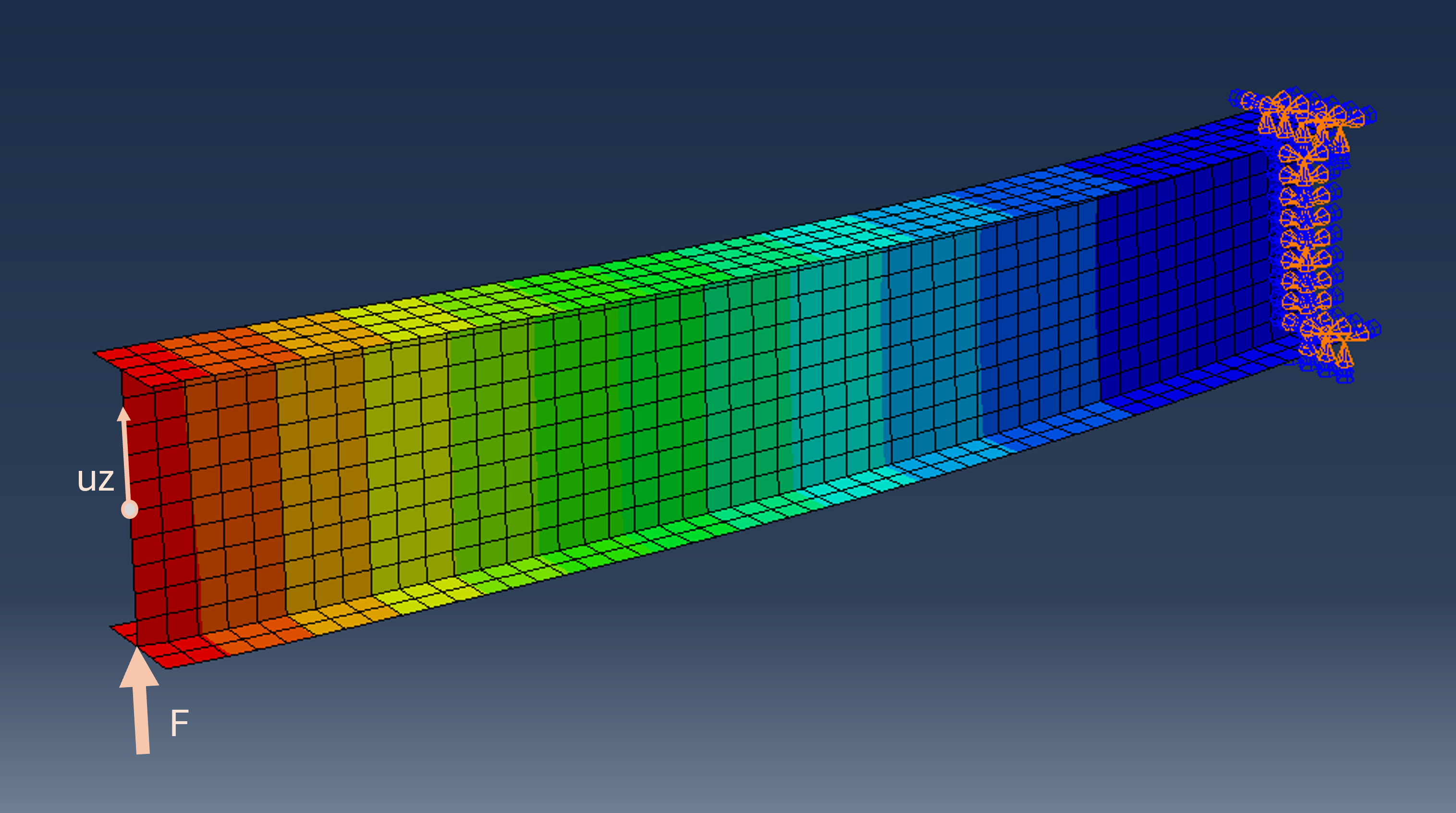
The model has only shell elements and has boundary conditions and loading corresponding to a cantilever beam subjected to a concentrated tip force.
Detailed description is given in the video
Abaqus scripting, I-profiles Part-1
from abaqus import *
from abaqusConstants import *
def iprofile(modelname, L, bb, bt, h, tf, tw, offs, esize, F):
mod = mdb.Model(name=modelname, modelType=STANDARD_EXPLICIT)
# Part
ske = mod.ConstrainedSketch(name='__profile__', sheetSize=200.0)
ske.Line(point1=(-bb/2.0, -h/2.0), point2=(bb/2.0, -h/2.0))
ske.Line(point2=(-bt/2.0, h/2.0), point1=(bt/2.0, h/2.0))
ske.Line(point1=(0.0, -h/2.0), point2=(0.0, h/2.0))
prt = mod.Part(name='IProfile', dimensionality=THREE_D, type=DEFORMABLE_BODY)
prt.BaseShellExtrude(sketch=ske, depth=L)
del mod.sketches['__profile__']
# Partition
id = prt.DatumPlaneByPrincipalPlane(principalPlane=XZPLANE, offset=0.0).id
prt.PartitionFaceByDatumPlane(datumPlane=prt.datums[id], faces=prt.faces)
# Material and section
mat = mod.Material(name='Alu')
mat.Elastic(table=((70000.0, 0.33), ))
mod.HomogeneousShellSection(name='Sec-fla',
preIntegrate=OFF, material='Alu', thicknessType=UNIFORM, thickness=tf,
thicknessField='', nodalThicknessField='',
idealization=NO_IDEALIZATION, poissonDefinition=DEFAULT,
thicknessModulus=None, temperature=GRADIENT, useDensity=OFF,
integrationRule=SIMPSON, numIntPts=5)
mod.HomogeneousShellSection(name='Sec-web',
preIntegrate=OFF, material='Alu', thicknessType=UNIFORM, thickness=tw,
thicknessField='', nodalThicknessField='',
idealization=NO_IDEALIZATION, poissonDefinition=DEFAULT,
thicknessModulus=None, temperature=GRADIENT, useDensity=OFF,
integrationRule=SIMPSON, numIntPts=5)
# Sets
setall = prt.Set(faces=prt.faces, name='faces-all')
setbot = prt.Set(faces=prt.faces.getByBoundingBox(yMax=-h/2.0), name='faces-bottm-flange')
settop = prt.Set(faces=prt.faces.getByBoundingBox(yMin= h/2.0), name='faces-top-flange')
setfla = prt.SetByBoolean(sets=(setbot,settop), name='faces-flanges')
setweb = prt.SetByBoolean(sets=(setall, setfla), operation=DIFFERENCE, name='faces-web')
# Section assignments
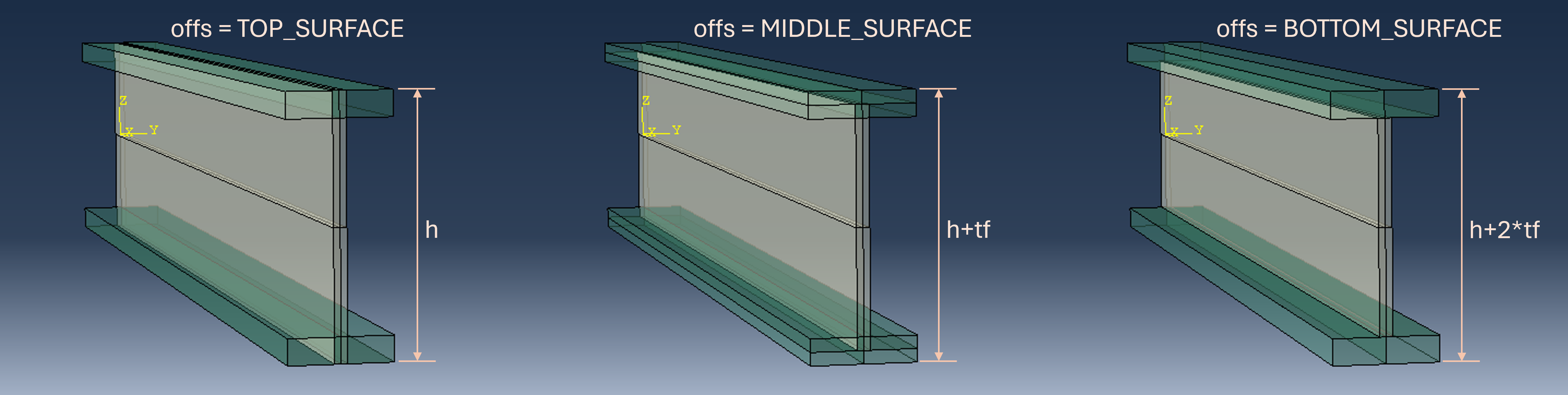
prt.SectionAssignment(region=setfla, sectionName='Sec-fla', offset=0.0,
offsetType=offs, offsetField='', thicknessAssignment=FROM_SECTION)
prt.SectionAssignment(region=setweb, sectionName='Sec-web', offset=0.0,
offsetType=MIDDLE_SURFACE, offsetField='', thicknessAssignment=FROM_SECTION)
# Mesh
prt.setMeshControls(regions=prt.faces, elemShape=QUAD, technique=STRUCTURED)
prt.seedPart(size=esize, deviationFactor=0.1, minSizeFactor=0.1)
prt.generateMesh()
# Assembly and constraints
ass = mod.rootAssembly
ass.DatumCsysByDefault(CARTESIAN)
ins = ass.Instance(name='IProfile', part=prt, dependent=ON)
ass.rotate(instanceList=('IProfile', ), axisPoint=(0.0, 0.0, 0.0), axisDirection=(0.0, 1.0, 0.0), angle=90.0)
ass.rotate(instanceList=('IProfile', ), axisPoint=(0.0, 0.0, 0.0), axisDirection=(1.0, 0.0, 0.0), angle=90.0)
# Set of center node at end 2
v = ins.vertices.findAt(((L, 0.0, 0.0), ))
ass.Set(vertices=v, name='MONITORPOINT')
# Fix one end
edges=ins.edges.getByBoundingBox(xMax=0.0)
region = ass.Set(edges=edges, name = 'EDGES1')
bc1 = mod.DisplacementBC(name='FIXEDEND', createStepName='Initial',
region=region, u1=SET, u2=SET, u3=SET, ur1=SET, ur2=SET, ur3=SET)
# Step and loading
mod.StaticStep(name='Step-Stat', previous='Initial')
v = ins.vertices.findAt(((L, 0.0, -h/2.0), ))
region = ass.Set(vertices=v, name='POINLOAD')
mod.ConcentratedForce(name='PointForce', createStepName='Step-Stat',
region=region, cf3=F, distributionType=UNIFORM, field='', localCsys=None)
# Job
job = mdb.Job(name=modelname, model=modelname)
job.submit(consistencyChecking=OFF)
job.waitForCompletion()
# Result
odb = session.openOdb(name=modelname+'.odb')
region = odb.rootAssembly.nodeSets['MONITORPOINT']
uz = odb.steps['Step-Stat'].frames[-1].fieldOutputs['U'].getSubset(region=region).values[0].data[2]
print 'Model: {}, uz = {}'.format(modelname, uz)
Study
The difference between the different strategies for shell offset:
iprofile(modelname='M001', L=100, bb=8, bt=8, h=20, tf=2, tw=1, offs=TOP_SURFACE,    esize=2, F=1000)
iprofile(modelname='M002', L=100, bb=8, bt=8, h=18, tf=2, tw=1, offs=MIDDLE_SURFACE, esize=2, F=1000)
iprofile(modelname='M003', L=100, bb=8, bt=8, h=16, tf=2, tw=1, offs=BOTTOM_SURFACE, esize=2, F=1000)
Print-out from the script:
Model: M001, uz = 1.67774868011
Model: M002, uz = 1.74466669559
Model: M003, uz = 1.81191015244
Realize that the web contributes for a significant part of the structural bending stiffness, making first model significantly stiffer than the third model:
# Relative structural stiffness:
uz_1 = 1.67774868011
uz_2 = 1.74466669559
uz_3 = 1.81191015244
print('{:.1f}%  {:.1f}%   {:.1f}%'.format(  100/(uz_1/uz_3), 100/(uz_2/uz_3), 100/(uz_3/uz_3)  )   )
For long, slender beams, the difference can be attributed to the difference in bending stiffness (minor contribution from shear deformation):
iprofile(modelname='M011', L=1000, bb=8, bt=8, h=20, tf=2, tw=1, offs=TOP_SURFACE,    esize=2, F=10)
iprofile(modelname='M012', L=1000, bb=8, bt=8, h=18, tf=2, tw=1, offs=MIDDLE_SURFACE, esize=2, F=10)
iprofile(modelname='M013', L=1000, bb=8, bt=8, h=16, tf=2, tw=1, offs=BOTTOM_SURFACE, esize=2, F=10)
uz_1 = 14.61101341
uz_2 = 15.45566082
uz_3 = 16.21745109
print('{:.1f}%  {:.1f}%   {:.1f}%'.format(  100/(uz_1/uz_3), 100/(uz_2/uz_3), 100/(uz_3/uz_3)  )   )
Relative bending stiffness can easilly be estimated, and the results are very consistent with the FEA results:
# Bending stiffness, manual estimate:

Db_1 = 70000*( (8*20**3)/12 - (8*16**3)/12 + (1*20**3)/12  )
Db_2 = 70000*( (8*20**3)/12 - (8*16**3)/12 + (1*18**3)/12  )
Db_3 = 70000*( (8*20**3)/12 - (8*16**3)/12 + (1*16**3)/12  )

print('{:.1f}%  {:.1f}%   {:.1f}%'.format(  100*Db_1/Db_3, 100*Db_2/Db_3, 100*Db_3/Db_3  )   )
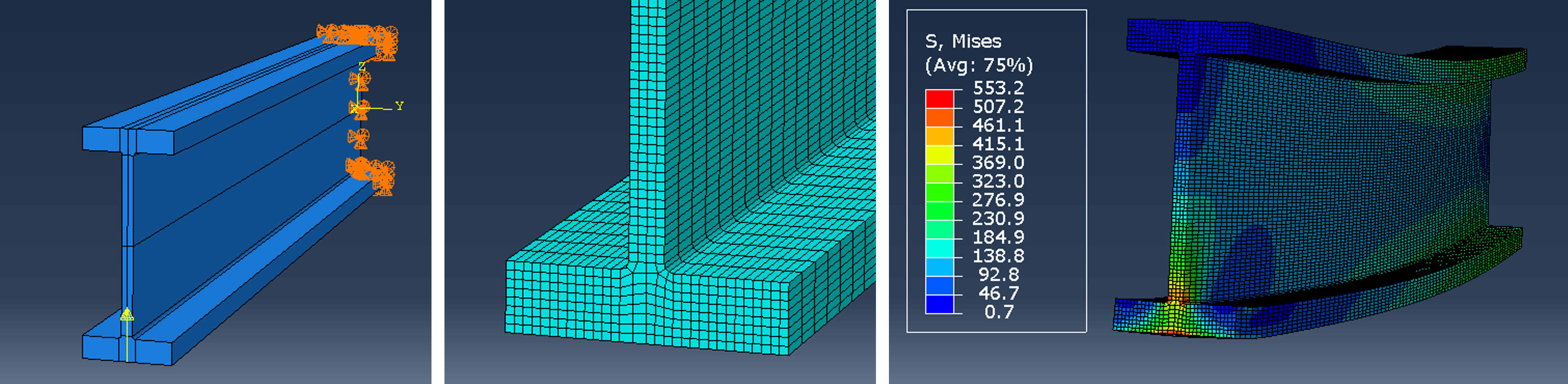
The point load as implemented on a single node may prevent a realistic comparison of local stresses. Therefore, a modification that utilize coupling can be implemented, see the video Abaqus scripting, I-profiles Part-2.
Replace the # Step and loading segment with the following lines:
    # Step and loading
    mod.StaticStep(name='Step-Stat', previous='Initial')
    v = ins.vertices.findAt(((L, 0.0, -h/2.0), ))
    regionP = ass.Set(vertices=v, name='POINLOAD')
    edges = ins.edges.getByBoundingBox(xMin=L, zMax=-h/2.0)
    regionE=ass.Set(edges=edges, xVertices=v, name='CPEdges')
    mod.Coupling(name='Coupling', controlPoint=regionP,
        surface=regionE, influenceRadius=WHOLE_SURFACE, couplingType=KINEMATIC,
        localCsys=None, u1=OFF, u2=OFF, u3=ON, ur1=OFF, ur2=OFF, ur3=OFF)
    mod.ConcentratedForce(name='PointForce', createStepName='Step-Stat',
        region=regionP, cf3=F, distributionType=UNIFORM, field='', localCsys=None)
The effect is that while the force is imposed on a single node, the force will be distributed to all nodes on the tip edge of the bottom flange:
iprofile(modelname='M001b', L=100, bb=8, bt=8, h=20, tf=2, tw=1, offs=TOP_SURFACE,    esize=2, F=1000)
iprofile(modelname='M002b', L=100, bb=8, bt=8, h=18, tf=2, tw=1, offs=MIDDLE_SURFACE, esize=2, F=1000)
iprofile(modelname='M003b', L=100, bb=8, bt=8, h=16, tf=2, tw=1, offs=BOTTOM_SURFACE, esize=2, F=1000)
A slightly less stress concentration is observed for the modification (M001b) compared to the original point load implementation (M001).
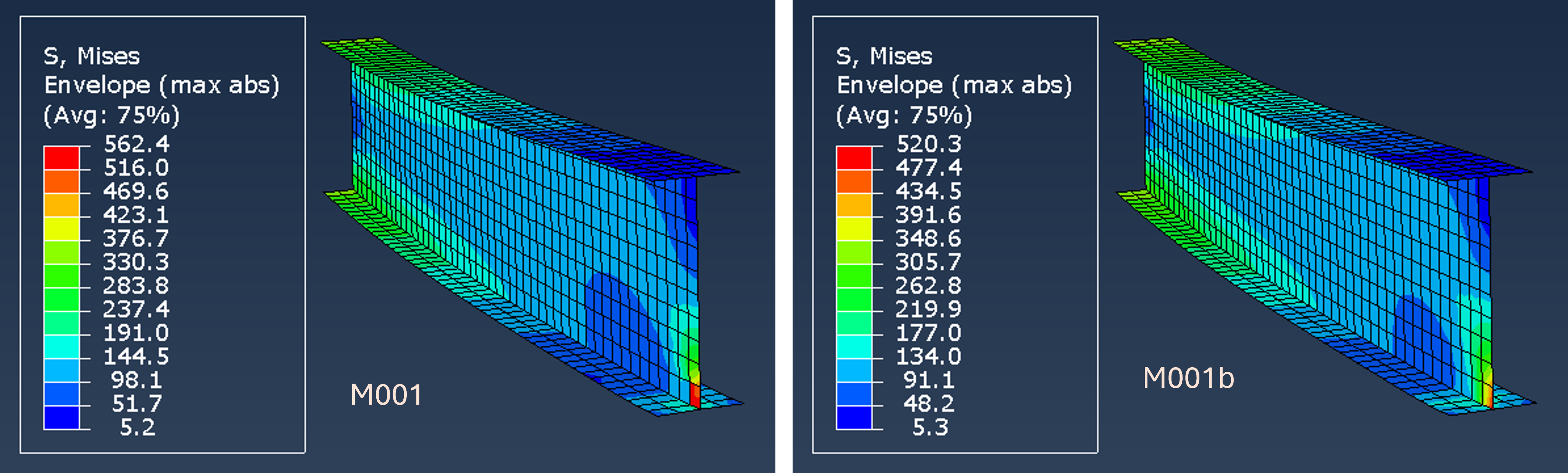
Selecting some elements far from the ends, approximatly at the middle of the beam:
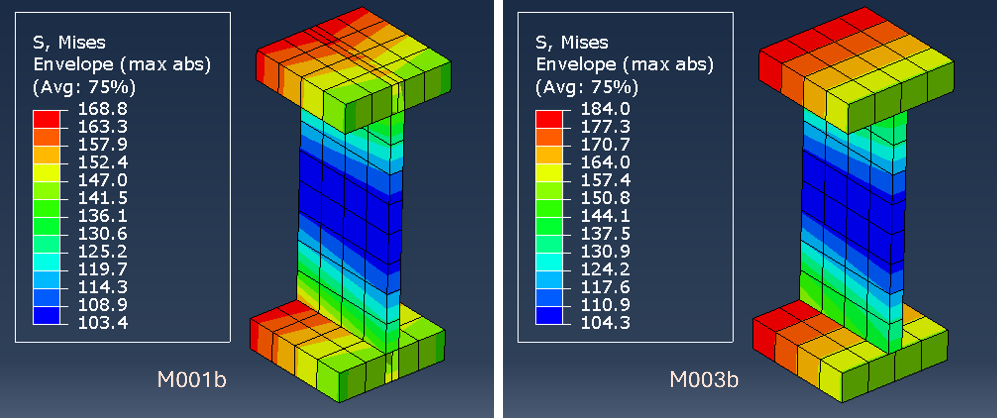
The model with shell offset TOP_SURFACE (M003b) has higher stresses than the model with shell offset BOTTOM_SURFACE (M001b). The explanation follows the same argument as for the difference in structural stiffness: The model M001b has more volume (material) than M003b.
Model-2: Basic solid model
Detailed description is given in the video Abaqus scripting, I-profiles Part-3
from abaqus import *
from abaqusConstants import *
from part import EdgeArray

def iprofileSol(modelname, L, b, h, tf, tw, rfil, esize, F):
    '''
    L:     Length
    b:     Width, flanges
    h:     Height
    tf:    Thickness, flanges
    tw:    Thickness, web
    rfil:  Fillet radius
    esize: Globale element size
    F:     Tip force assuming a cantilever beam configuration
    '''
    mod = mdb.Model(name=modelname, modelType=STANDARD_EXPLICIT)

    # Part
    ske = mod.ConstrainedSketch(name='__profile__', sheetSize=200.0)
    ske.Line(point1=(0.0, 0.0), point2=(tw/2.0, 0.0))
    ske.Line(point1=(tw/2.0, 0.0), point2=(tw/2.0, h/2.0-tf-rfil))
    ske.ArcByCenterEnds(center=(tw/2.0+rfil, h/2.0-tf-rfil), point1=(tw/2.0, h/2.0-tf-rfil),
        point2=(tw/2.0+rfil, h/2.0-tf), direction=CLOCKWISE)
    ske.Line(point1=(tw/2.0+rfil, h/2.0-tf), point2=(b/2.0, h/2.0-tf))
    ske.Line(point1=(b/2.0, h/2.0-tf), point2=(b/2.0, h/2.0))
    ske.Line(point1=(b/2.0, h/2.0), point2=(0.0, h/2.0))
    ske.Line(point1=(0.0, h/2.0), point2=(0.0, 0.0))
    prt = mod.Part(name='Ibeam', dimensionality=THREE_D, type=DEFORMABLE_BODY)
    prt.BaseSolidExtrude(sketch=ske, depth=L)
    del mod.sketches['__profile__']

    # Partition and mirror
    id = prt.DatumPlaneByPrincipalPlane(principalPlane=XZPLANE, offset=h/2.0-tf-rfil).id
    prt.PartitionCellByDatumPlane(datumPlane=prt.datums[id], cells=prt.cells)
    id = prt.DatumPlaneByPrincipalPlane(principalPlane=YZPLANE, offset=tw/2.0+rfil).id
    prt.PartitionCellByDatumPlane(datumPlane=prt.datums[id], cells=prt.cells)
    prt.Mirror(mirrorPlane=prt.faces.findAt(coordinates=(0.0, (h-tf-rfil)/2.0, L/2.0)),
        keepOriginal=ON, keepInternalBoundaries=ON)
    prt.Mirror(mirrorPlane=prt.faces.findAt(coordinates=(tw/4.0, 0.0, L/2.0)),
        keepOriginal=ON, keepInternalBoundaries=ON)

    # Mesh
    edges = EdgeArray([e for e in prt.edges if e.pointOn[0][2]>0.0 and e.pointOn[0][2]<L])
    prt.seedEdgeBySize(edges=edges, size=5*esize, deviationFactor=0.1, constraint=FINER)
    prt.seedPart(size=esize, deviationFactor=0.1, minSizeFactor=0.1)
    prt.generateMesh()

   # Material and section
    mat = mod.Material(name='Alu')
    mat.Elastic(table=((70000.0, 0.33), ))
    mod.HomogeneousSolidSection(name='SecSol',  material='Alu')
    region = prt.Set(cells=prt.cells, name='cells-all')
    prt.SectionAssignment(region=region, sectionName='SecSol', thicknessAssignment=FROM_SECTION)

    # Assembly and constraints
    ass = mod.rootAssembly
    ass.DatumCsysByDefault(CARTESIAN)
    ins = ass.Instance(name='Ibeam', part=prt, dependent=ON)
    ass.rotate(instanceList=('Ibeam', ), axisPoint=(0.0, 0.0, 0.0), axisDirection=(0.0, 1.0, 0.0), angle=90.0)
    ass.rotate(instanceList=('Ibeam', ), axisPoint=(0.0, 0.0, 0.0), axisDirection=(1.0, 0.0, 0.0), angle=90.0)

    # Set of center node at end 2
    v = ins.vertices.findAt(((L, 0.0, 0.0), ))
    ass.Set(vertices=v, name='MONITORPOINT')

    # Fix one end
    faces=ins.faces.getByBoundingBox(xMax=0.0)
    region = ass.Set(faces=faces, name = 'EDGE1FACES')
    bc1 = mod.DisplacementBC(name='FIXEDEND', createStepName='Initial',
        region=region, u1=SET, u2=SET, u3=SET)

    # Step and loading
    mod.StaticStep(name='Step-Stat', previous='Initial')
    v = ins.vertices.findAt(((L, 0.0, -h/2.0), ))
    regionP = ass.Set(vertices=v, name='POINLOAD')
    edges = ins.edges.getByBoundingBox(xMin=L, zMax=-h/2.0)
    regionE=ass.Set(edges=edges, xVertices=v, name='CPEdges')
    mod.Coupling(name='Coupling', controlPoint=regionP,
        surface=regionE, influenceRadius=WHOLE_SURFACE, couplingType=KINEMATIC,
        localCsys=None, u1=OFF, u2=OFF, u3=ON, ur1=OFF, ur2=OFF, ur3=OFF)
    mod.ConcentratedForce(name='PointForce', createStepName='Step-Stat',
        region=regionP, cf3=F, distributionType=UNIFORM, field='', localCsys=None)

    # Job
    job = mdb.Job(name=modelname, model=modelname)
    job.submit(consistencyChecking=OFF)
    job.waitForCompletion()
    odb = session.openOdb(name=modelname+'.odb')
    region = odb.rootAssembly.nodeSets['MONITORPOINT']
    uz = odb.steps['Step-Stat'].frames[-1].fieldOutputs['U'].getSubset(region=region).values[0].data[2]
    print 'Model: {}, uz = {}'.format(modelname, uz)

iprofileSol(modelname='S001', L=100, b=8, h=20, tf=2, tw=1, rfil=0.25, esize=0.25, F=1000)
The model created by the parameters in the script is comparable to M001b, M002b and M003b.
Displacement for the node at x=L, y=z=0:
Model: S001, uz = 1.8010699749


