Layered solid pipe
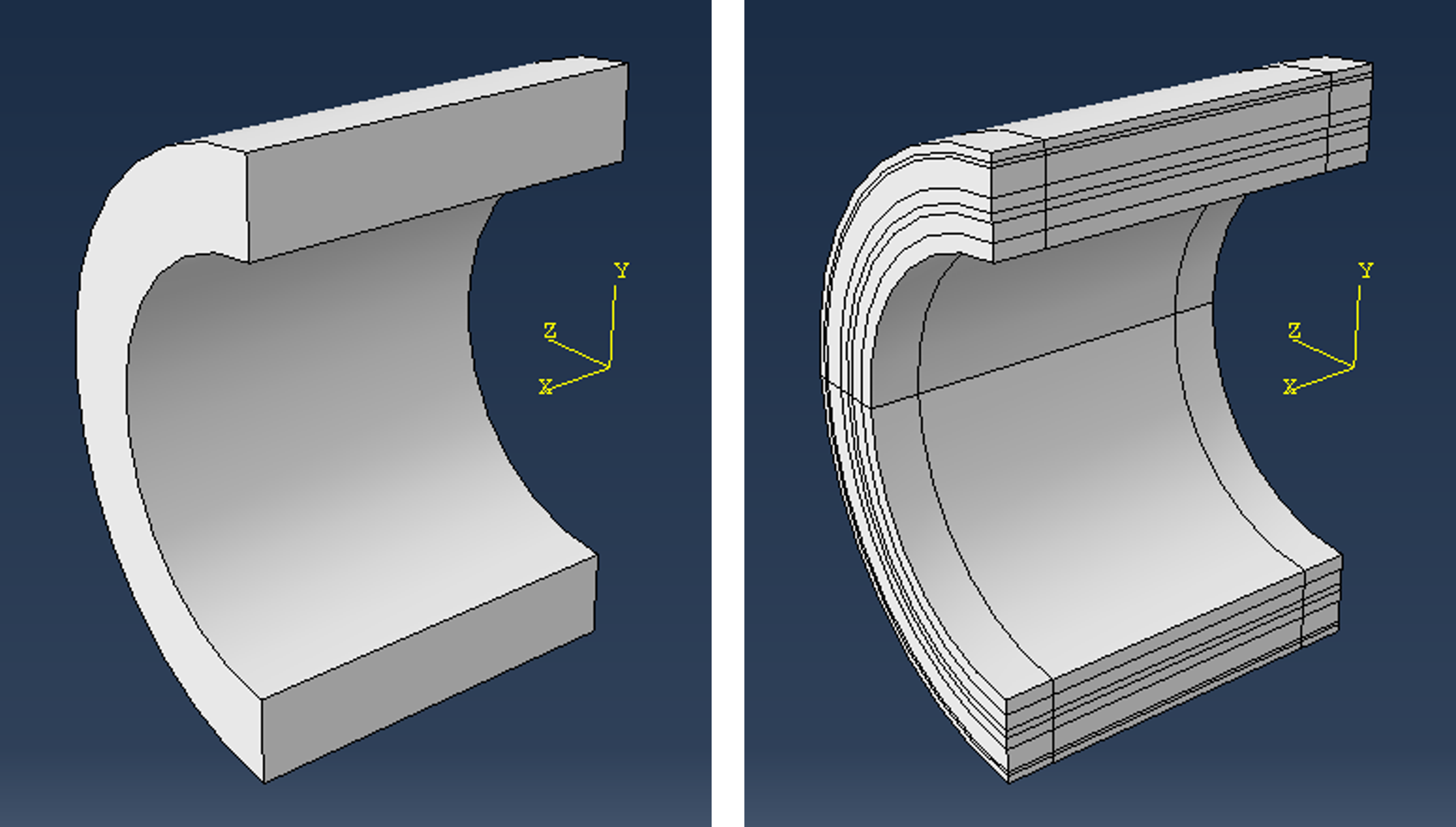
Features and assumptions
- Symmetry about the xy-plane.
- Any number of layers through the thickness
- The different layers may have different materials
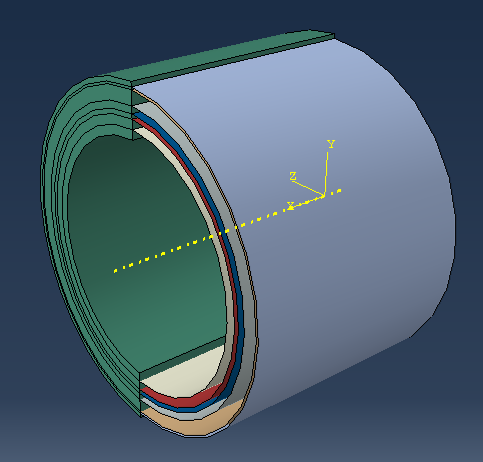
- Separate regions at both ends
- Separate regions below the xz-plane and above the xz-plane
Geometry parameters
L: the length of the piperi: the internal radiustk: a sequence of layer thicknessesdxe: the length of the regions at the ends
Modeling approach
Create a half cylinder using BaseSolidRevolve() where the axis of revolution is a construction line along the x-axis. The are to revolve is a rectangle where the outermost y-coordinate is the outer radius that is computed as
ro = ri + sum(tk) # outer radius
from abaqus import *
from abaqusConstants import *

def multiLayeredPipe(modelname, L, ri, tk, dxe):

    ro =  ri + sum(tk)  # outer radius

    # Creating the solid pipe

    mod = mdb.Model(name=modelname)
    ske = mod.ConstrainedSketch(name='__profile__', sheetSize=200.0)
    ske.ConstructionLine(point1=(0.0, 0.0), point2=(100.0, 0.0))
    ske.rectangle(point1=(0.0, ri), point2=(L, ro))
    prt = mod.Part(name='Base', dimensionality=THREE_D, type=DEFORMABLE_BODY)
    prt.BaseSolidRevolve(sketch=ske, angle=180.0, flipRevolveDirection=OFF)
    del mod.sketches['__profile__']

multiLayeredPipe(modelname='M1', L=100.0, ri=50.0, tk = (4.0, 4.0, 2.0, 3.0, 6.0, 1.0, 2.0), dxe=12.5)
The required partitions can be obtained in several different ways and in different sequences. It is however likely that doing the partition of layers before anything else is the easiest approach. Some alternatives:
- Partition the surface at one of the end by sketching arcs that are extruded along the x-direction
- Partition one of the surfaces at in the xy-plan by sketching lines that er revolved along a circular edge
- Creating shell cylinder parts and using boolean cut in the assembly.
From a scripting perspective, the last alternative is probably the simplest. First, add the solid part 'Base' to the assembly:
    # Assembly

    ass = mod.rootAssembly
    ass.DatumCsysByDefault(CARTESIAN)
    ins_base = ass.Instance(name='Base', part=prt, dependent=ON)
Then, create shell cylinder parts representing the interface between the layers, and add those to the assembly:
    # Shell cylinders for dividing the base into layers cell

    r = ri
    cut_instances=[]
    for i in range(0, len(tk)-1):
        r = r + tk[i]
        ske = mod.ConstrainedSketch(name='__profile__', sheetSize=200.0)
        ske.ConstructionLine(point1=(0.0, 0.0), point2=(100.0, 0.0))
        ske.Line(point1=(0.0, r), point2=(L, r))
        p = mod.Part(name='CP'+str(i+1), dimensionality=THREE_D, type=DEFORMABLE_BODY)
        p.BaseShellRevolve(sketch=ske, angle=360.0, flipRevolveDirection=OFF)
        del mod.sketches['__profile__']
        cut_instances.append(ass.Instance(name=p.name, part=p,  dependent=ON))
Note that the instances are stored in the list cut_instances which is needed for boolean operation later on.
The assembly has now all the additional shell cylinders, and the idea is to use these to cut the solid base part using
InstanceFromBooleanCut()As indicated, the method creates a new instance and a new part. The new part 'Pipe' will be the active part to work on further.
The parameter cuttingInstances requires a tuple, not a list, and therefore cuttingInstances = tuple(cut_instances).
    # Boolean cut

    ass.InstanceFromBooleanCut(name='Pipe', instanceToBeCut=ins_base,
        cuttingInstances=tuple(cut_instances), originalInstances=SUPPRESS)
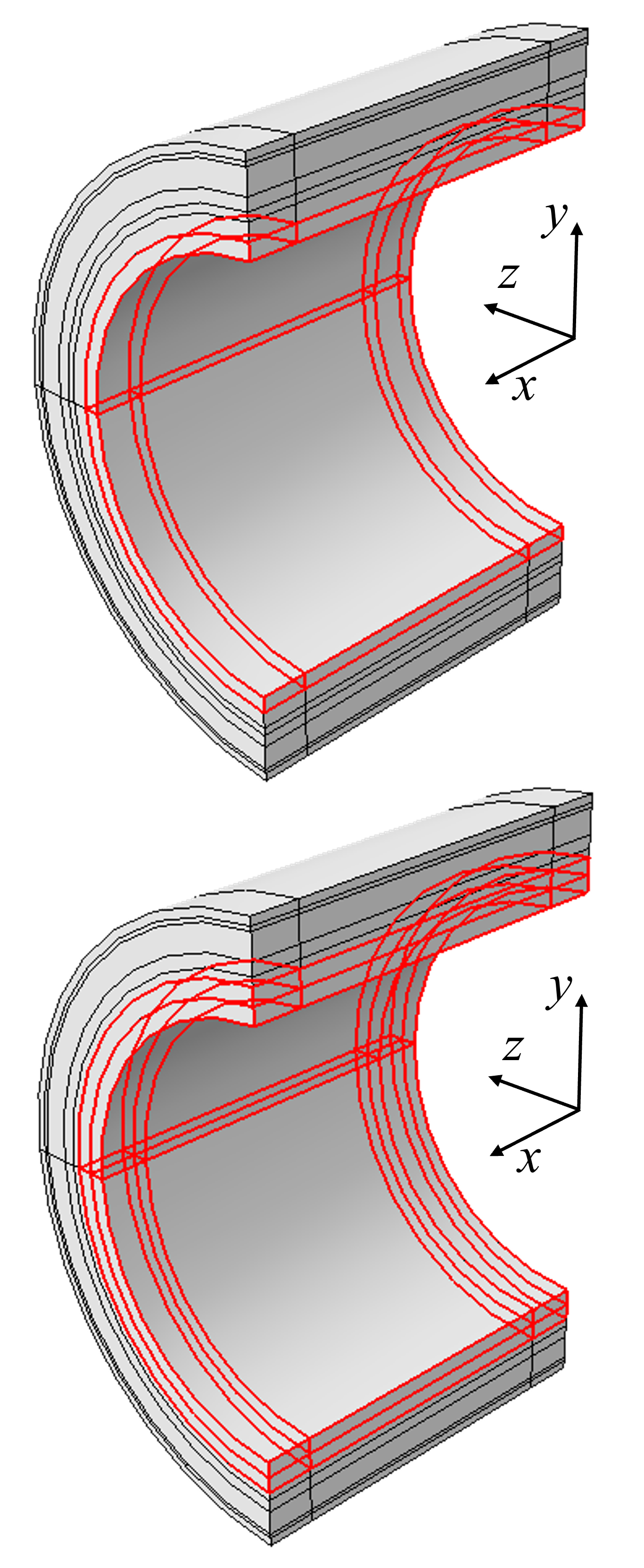
The final partitions are simply obtained by using datum planes:
    # Partitions by planes

    prt = mod.parts['Pipe']
    id=prt.DatumPlaneByPrincipalPlane(principalPlane=YZPLANE, offset=dxe).id
    prt.PartitionCellByDatumPlane(datumPlane=prt.datums[id], cells=prt.cells)
    id=prt.DatumPlaneByPrincipalPlane(principalPlane=YZPLANE, offset=L-dxe).id
    prt.PartitionCellByDatumPlane(datumPlane=prt.datums[id], cells=prt.cells)
    id=prt.DatumPlaneByPrincipalPlane(principalPlane=XZPLANE, offset=0.0).id
    prt.PartitionCellByDatumPlane(datumPlane=prt.datums[id], cells=prt.cells)
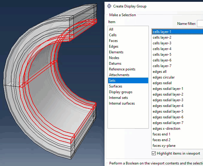
Creating sets and surfaces
Developing the code using the command line interface:
>>> prt = mdb.models['M1'].parts['Pipe']
>>> L = 100.0
>>> ri = 50.0
>>> tk = (4.0, 4.0, 2.0, 3.0, 6.0, 1.0, 2.0)
>>> dxe = 12.5
Cells
Selecting the cells belonging to the first layer is straight forward, for instance by
>>> radius = ri + tk[0]
>>> cells1 = prt.cells.getByBoundingCylinder(center1=(0,0,0), center2=(L,0,0), radius=radius)
>>> prt.Set(name='cells layer-1', cells=cells1)
Selecting the cells of the second layer is, however, more involved since the method getByBoundingCylinder() does not take an inner radius as argument. The following approach will therefore select both the first and the second layer:
>>> radius = ri + tk[0] + tk[1]
>>> cells2 = prt.cells.getByBoundingCylinder(center1=(0,0,0), center2=(L,0,0), radius=radius)
>>> prt.Set(name='cells layer-1-2', cells=cells2)
Then, we can solve the challenge by using boolean operation on sets:
>>> set_1_1 = prt.sets['cells layer-1-2']
>>> set_1   = prt.sets['cells layer-1']
>>> prt.SetByBoolean(name='cells layer-2', sets=(set_1_1, set_1), operation=DIFFERENCE)
While the method above will work, it is somewhat involved and the logic is a bit complicated to write for any random number of layers. A procedure that loops over all the cells and sorts by the coordinates of the property pointOn could be an easier task.
Firstly, a simple function to compute the radial position of any pointOn tuple:
>>> def radialpos(pointOn): return (pointOn[0][1]**2+pointOn[0][2]**2)**0.5A list of radial position, and the first five values of it:
>>> rpos = [radialpos(c.pointOn) for c in prt.cells]
>>> rpos[0:5]
[69.666667, 67.0, 62.0, 58.9999798975512, 61.7325867637319]
Now we can create a list of cell indices, and sort the list of indices by the radial positions:
>>> inds = [c.index for c in prt.cells]
>>> sorted_inds = [i for _, i in sorted(zip(rpos,inds))]
>>> sorted_inds
[19, 37, 40, 41, 17, 39, 38, 14, 16, 34, 36, 18, 35, 3, 13, 23, 33, 15, 22, 4,
 12, 24, 32, 2, 21, 5, 11, 25, 31, 1, 20, 6, 10, 26, 30, 0, 7, 29, 8, 9, 27, 28]
There are six celle per layer. Thus, the first six in the list belongs to the first layer:
>>> [radialpos(prt.cells[i].pointOn) for i in sorted_inds[0:6]]
[50.0000002029877, 50.0000002029877, 50.0000002029877, 51.333333, 52.3687674546412, 52.3687674546412]
The next layer (6-12) has the following radial positions:
>>> [radialpos(prt.cells[i].pointOn) for i in sorted_inds[6:12]]
[55.333333, 56.3464114623883, 56.3464114623883, 56.3464114623883, 56.3464114623883, 56.666667]
The complete code for this technique:
    # Sets and surfaces

    # Cells
    def radialpos(pointOn): return (pointOn[0][1]**2+pointOn[0][2]**2)**0.5
    rpos = [radialpos(c.pointOn) for c in prt.cells]
    npl = len(rpos)/len(tk)
    inds = [c.index for c in prt.cells]
    sorted_inds = [i for _, i in sorted(zip(rpos,inds))]
    for k in range(0, len(tk)):
        cArray = CellArray([prt.cells[i] for i in sorted_inds[k*npl:(k+1)*npl]])
        prt.Set(name='cells layer-'+str(k+1), cells=cArray)
Faces
The faces in the xy-plane can be selected using various alternative approaches. For example by picking faces where the z-koordinate of pointOn[0] is zero:
    faces = [f for f in prt.faces if f.pointOn[0][2] == 0]
    prt.Set(name='faces xy-plane', faces=faces)
Alternatively, using getByPO() from customtools:
    from customtools import getByPO
    prt.Set(name='faces xy-plane', faces=getByPO(prt.faces,z=0))
By the same method, the faces at both ends of the pipe:
    prt.Set(name='faces end 1', faces=getByPO(prt.faces,x=0))
    prt.Set(name='faces end 2', faces=getByPO(prt.faces,x=L))
Inner surface and outer surface of the pipe can most easily be selected using getByR() from customtools:
    prt.Surface(name='surface inner', side1Faces=getByR(prt.faces, r=ro))
prt.Surface(name='surface outer', side1Faces=getByR(prt.faces, r=ri)) # Faces
prt.Set(name='faces xy-plane', faces=getByPO(prt.faces,z=0))
prt.Set(name='faces end 1', faces=getByPO(prt.faces,x=0))
prt.Set(name='faces end 2', faces=getByPO(prt.faces,x=L))
prt.Surface(name='surface inner', side1Faces=getByR(prt.faces, r=ro))
prt.Surface(name='surface outer', side1Faces=getByR(prt.faces, r=ri))
Edges
It is required to control the size or number of elements along the different edges and/or directions.
There are no built in method or property for the direction of straight edges, but such a method is easy to create: An edge has two vertices that is retrived by the built-in method ...edges[i].getVertices(). The method returns the indices of the two vertices, and then the coordinates of the vertices can be used to construct the vector from one point to the other:
edges_x_direction = []
for e in prt.edges:
i1, i2 = e.getVertices()
c1, c2 = prt.vertices[i1].pointOn[0], prt.vertices[i2].pointOn[0]
if c1[1]-c2[1] == 0.0 and c1[2]-c2[2] == 0.0:
edges_x_direction.append(e)The function getByR() from customtools with no radius given as argument, will return all edges with any radius; that is, all edges not being straight. Then, boolean operations on sets will sort out all edges running in the radial direction (the ones that are left).
Finally, radial edges in individual layers can be identified using sorting based on radial position similar to what was done for cells in the layers:
# Edges
edges_x_direction = []
for e in prt.edges:
i1, i2 = e.getVertices()
c1, c2 = prt.vertices[i1].pointOn[0], prt.vertices[i2].pointOn[0]
if c1[1]-c2[1] == 0.0 and c1[2]-c2[2] == 0.0:
edges_x_direction.append(e)
setX = prt.Set(name='edges x-direction', edges = EdgeArray(edges_x_direction))
setA = prt.Set(name='edges all', edges=prt.edges)
setC = prt.Set(name='edges circular', edges=getByR(prt.edges))
prt.SetByBoolean(name='edges radial', sets=(setA, setX, setC), operation=DIFFERENCE)
rpos = [radialpos(e.pointOn) for e in prt.sets['edges radial'].edges]
npl = len(rpos)/len(tk)
inds = [e.index for e in prt.sets['edges radial'].edges]
sorted_inds = [i for _, i in sorted(zip(rpos,inds))]
for k in range(0, len(tk)):
eArray = EdgeArray([prt.edges[i] for i in sorted_inds[k*npl:(k+1)*npl]])
prt.Set(name='edges radial layer-'+str(k+1), edges=eArray)
Visualization
Properties
For the purpose of demonstration: Create two materials with corresponding sections and assigne the sections to layers in a alternating sequence:
# Properties
mat1 = mod.Material(name='Steel')
mat1.Elastic(table=((200000, 0.3),))
mat2 = mod.Material(name='PE')
mat2.Elastic(table=((1000, 0.35),))
mod.HomogeneousSolidSection(name='SecSteel', material='Steel', thickness=None)
mod.HomogeneousSolidSection(name='SecPE', material='PE', thickness=None)
secname='SecSteel'
for k in range(0, len(tk)):
prt.SectionAssignment(region=prt.sets['cells layer-'+str(k+1)], sectionName=secname,
offset=0.0, offsetType=MIDDLE_SURFACE, offsetField='', thicknessAssignment=FROM_SECTION)
if secname == 'SecSteel':
secname = 'SecPE'
else:
secname = 'SecSteel'
Mesh
Set the global element size to 5.0 and the element size in radial direction to 1.0 (those values should be included in the arguments of the function)
# Mesh
prt.seedPart(size=5.0, deviationFactor=0.1, minSizeFactor=0.1)
prt.seedEdgeBySize(edges=prt.sets['edges radial'].edges, size=1.0, deviationFactor=0.1,
minSizeFactor=0.1, constraint=FINER)
prt.generateMesh()
Complete script
from abaqus import *
from abaqusConstants import *
from part import CellArray, EdgeArray
from customtools import getByPO, getByR
def multiLayeredPipe(modelname, L, ri, tk, dxe, esize, esizeRad):
ro = ri + sum(tk) # outer radius
# Creating the solid pipe:
mod = mdb.Model(name=modelname)
ske = mod.ConstrainedSketch(name='__profile__', sheetSize=200.0)
ske.ConstructionLine(point1=(0.0, 0.0), point2=(100.0, 0.0))
ske.rectangle(point1=(0.0, ri), point2=(L, ro))
prt = mod.Part(name='Base', dimensionality=THREE_D, type=DEFORMABLE_BODY)
prt.BaseSolidRevolve(sketch=ske, angle=180.0, flipRevolveDirection=OFF)
del mod.sketches['__profile__']
# Assembly
ass = mod.rootAssembly
ass.DatumCsysByDefault(CARTESIAN)
ins_base = ass.Instance(name='Base', part=prt, dependent=ON)
# Shell cylinders for dividing the base into layers cell
r = ri
cut_instances=[]
for i in range(0, len(tk)-1):
r = r + tk[i]
ske = mod.ConstrainedSketch(name='__profile__', sheetSize=200.0)
ske.ConstructionLine(point1=(0.0, 0.0), point2=(100.0, 0.0))
ske.Line(point1=(0.0, r), point2=(L, r))
p = mod.Part(name='CP'+str(i+1), dimensionality=THREE_D, type=DEFORMABLE_BODY)
p.BaseShellRevolve(sketch=ske, angle=360.0, flipRevolveDirection=OFF)
del mod.sketches['__profile__']
cut_instances.append(ass.Instance(name=p.name, part=p, dependent=ON))
# Boolean cut
ass.InstanceFromBooleanCut(name='Pipe', instanceToBeCut=ins_base,
cuttingInstances=tuple(cut_instances), originalInstances=SUPPRESS)
# Partitions by planes
prt = mod.parts['Pipe']
id=prt.DatumPlaneByPrincipalPlane(principalPlane=YZPLANE, offset=dxe).id
prt.PartitionCellByDatumPlane(datumPlane=prt.datums[id], cells=prt.cells)
id=prt.DatumPlaneByPrincipalPlane(principalPlane=YZPLANE, offset=L-dxe).id
prt.PartitionCellByDatumPlane(datumPlane=prt.datums[id], cells=prt.cells)
id=prt.DatumPlaneByPrincipalPlane(principalPlane=XZPLANE, offset=0.0).id
prt.PartitionCellByDatumPlane(datumPlane=prt.datums[id], cells=prt.cells)
# Sets and surfaces
# Cells
def radialpos(pointOn): return (pointOn[0][1]**2+pointOn[0][2]**2)**0.5
rpos = [radialpos(c.pointOn) for c in prt.cells]
npl = len(rpos)/len(tk)
inds = [c.index for c in prt.cells]
sorted_inds = [i for _, i in sorted(zip(rpos,inds))]
for k in range(0, len(tk)):
cArray = CellArray([prt.cells[i] for i in sorted_inds[k*npl:(k+1)*npl]])
prt.Set(name='cells layer-'+str(k+1), cells=cArray)
    # Faces
    prt.Set(name='faces xy-plane', faces=getByPO(prt.faces,z=0))
    prt.Set(name='faces end 1', faces=getByPO(prt.faces,x=0))
    prt.Set(name='faces end 2', faces=getByPO(prt.faces,x=L))
    prt.Surface(name='surface inner', side1Faces=getByR(prt.faces, r=ro))
    prt.Surface(name='surface outer', side1Faces=getByR(prt.faces, r=ri))
# Edges
    edges_x_direction = []
    for e in prt.edges:
        i1, i2 = e.getVertices()
        c1, c2 = prt.vertices[i1].pointOn[0], prt.vertices[i2].pointOn[0]
        if c1[1]-c2[1] == 0.0 and c1[2]-c2[2] == 0.0:
            edges_x_direction.append(e)
setX = prt.Set(name='edges x-direction', edges = EdgeArray(edges_x_direction))
setA = prt.Set(name='edges all', edges=prt.edges)
setC = prt.Set(name='edges circular', edges=getByR(prt.edges))
prt.SetByBoolean(name='edges radial', sets=(setA, setX, setC), operation=DIFFERENCE)
rpos = [radialpos(e.pointOn) for e in prt.sets['edges radial'].edges]
npl = len(rpos)/len(tk)
inds = [e.index for e in prt.sets['edges radial'].edges]
sorted_inds = [i for _, i in sorted(zip(rpos,inds))]
for k in range(0, len(tk)):
eArray = EdgeArray([prt.edges[i] for i in sorted_inds[k*npl:(k+1)*npl]])
prt.Set(name='edges radial layer-'+str(k+1), edges=eArray)
    # Properties

    mat1 = mod.Material(name='Steel')
    mat1.Elastic(table=((200000, 0.3),))
    mat2 = mod.Material(name='PE')
    mat2.Elastic(table=((1000, 0.35),))
    mod.HomogeneousSolidSection(name='SecSteel', material='Steel', thickness=None)
    mod.HomogeneousSolidSection(name='SecPE', material='PE', thickness=None)
    secname='SecSteel'
    for k in range(0, len(tk)):
        prt.SectionAssignment(region=prt.sets['cells layer-'+str(k+1)], sectionName=secname,
            offset=0.0, offsetType=MIDDLE_SURFACE, offsetField='', thicknessAssignment=FROM_SECTION)
        if secname == 'SecSteel':
            secname = 'SecPE'
        else:
            secname = 'SecSteel'
# Mesh
prt.seedPart(size=esize, deviationFactor=0.1, minSizeFactor=0.1)
prt.seedEdgeBySize(edges=prt.sets['edges radial'].edges, size=esizeRad, deviationFactor=0.1,
minSizeFactor=0.1, constraint=FINER)
prt.generateMesh()
multiLayeredPipe(modelname='M1', L=100.0, ri=50.0, tk=(4.0,4.0,2.0,3.0,6.0,1.0,2.0), dxe=12.5, esize=5.0, esizeRad=1.0)


