Plate with a hole
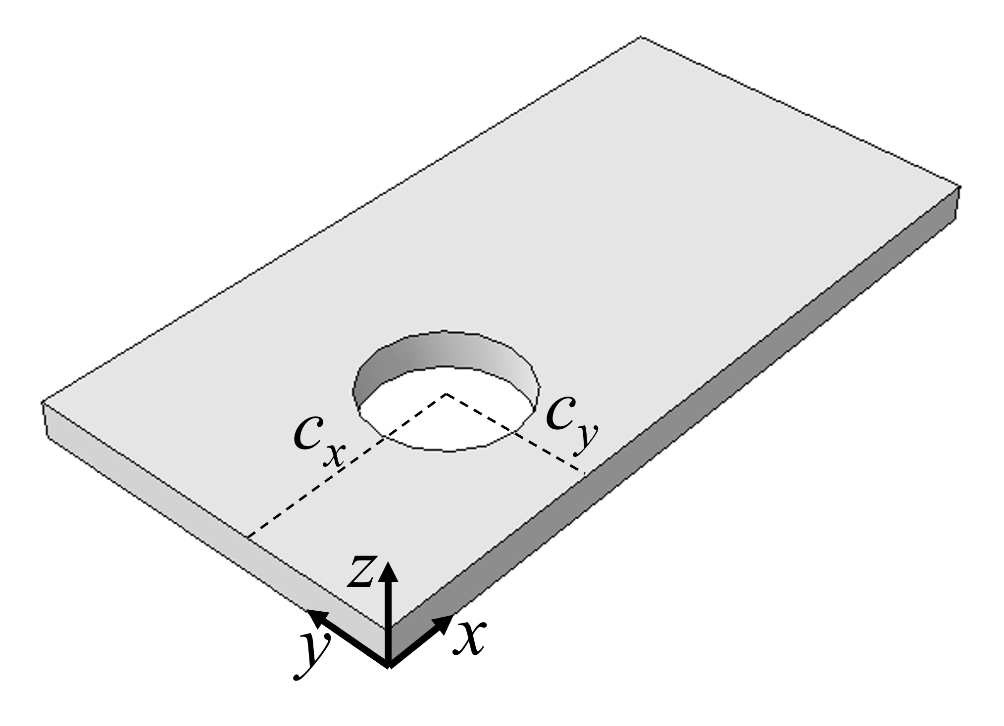
The geometry of a plate with a hole shall be fully described by the following parameters:
L: length (along x)b: width (along y)h: thickness (along z)r: radius of the holecx: x-coordinate to the center of the holecy: y-coordinate to the center of the hole
Since the hole can be anywhere, symmetry about xz-plane and/or yz-plane cannot be assumed and utilized. The plate can however be created using extrusion of only one sketch containing a rectangle and a circle.
from abaqus import *
from abaqusConstants import *

def plateWithHole(modelname, L, b, h, r, cx, cy):
    mod = mdb.Model(name=modelname)
    ske = mod.ConstrainedSketch(name='__profile__', sheetSize=200.0)
    ske.rectangle(point1=(0.0, 0.0), point2=(L, b))
    ske.CircleByCenterPerimeter(center=(cx, cy), point1=(cx+r, cy))
    prt = mod.Part(name='P1', dimensionality=THREE_D, type=DEFORMABLE_BODY)
    prt.BaseSolidExtrude(sketch=ske, depth=h)
    del mod.sketches['__profile__']
    session.viewports['Viewport: 1'].setValues(displayedObject=prt)

plateWithHole(modelname='M1', L=100.0, b=50.0, h=5.0, r=10.0, cx=30.0, cy=20.0)
Attempting to mesh the part will lead to an unstructured mesh as illustrated in the figure below.
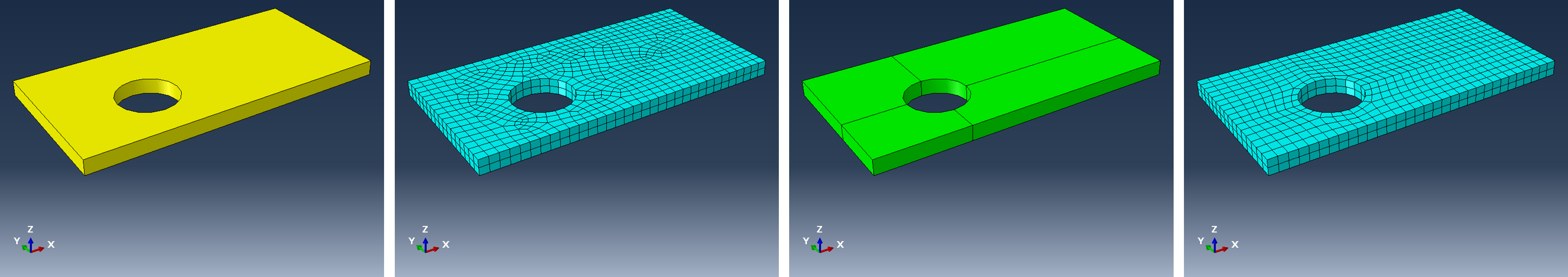
A structured mesh is often prefered as it enables higher quality of elements for the same seed (element size). Structure mesh can be obtained by simplifying the topolgy of cells, in this case by partitioning along planes running through the center of the hole. Several approaches for this task will be demonstrated here.
PartitionCellByDatumPlane(cells, datumePlane)
Datum planes are obviously needed, and the easiest method is to offset principal planes y-z and x-z by cx and cy respectively:
>>> cx, cy = 30.0, 20.0
>>> prt = mdb.models['M1'].parts['P1']
>>> plane1 = prt.DatumPlaneByPrincipalPlane(principalPlane=YZPLANE, offset=cx)
>>> plane2 = prt.DatumPlaneByPrincipalPlane(principalPlane=XZPLANE, offset=cy)
However, the method DatumPlaneByPrincipalPlane(...) does not return a datum plane as we may have anticipated, but rather a feature:
>>> type(plane1)
<type 'Feature'>
Hence, there is a repository for features
>>> type(prt.features)
<type 'Repository'>
and other features in the reposity of the part can be listed:
>>> print prt.features
{'Solid extrude-1': 'Feature object', 'Datum plane-1': 'Feature object', 'Datum plane-2': 'Feature object'}
>>> or
A feature object has an id,
>>> print prt.features['Datum plane-1']
({'children': '', 'id': 2, 'isOutOfDate': False, 'name': 'Datum plane-1', 'offset': 30.0, 'parents': '',
  'path': 'unknown', 'sketch': 'unknown'})
and this id is the key for the datum plane in the repository datums:
>>> print prt.datums
{2: 'DatumPlane object', 3: 'DatumPlane object'}
>>> type(prt.datums[2])
<type 'DatumPlane'>
>>> print prt.datums[2]
({'normal': (1.0, 0.0, 0.0), 'pointOn': (30.0, 0.0, 0.0)})
Hence, the two datume planes can be referenced by
>>> id1 = plane1.id
>>> id2 = plane2.id
>>> dp1 = prt.datums[id1]
>>> dp2 = prt.datums[id2]
The complete code following the existing code is therefore
plane1 = prt.DatumPlaneByPrincipalPlane(principalPlane=YZPLANE, offset=cx)
    plane2 = prt.DatumPlaneByPrincipalPlane(principalPlane=XZPLANE, offset=cy)
    id1 = plane1.id
    id2 = plane2.id
    dp1 = prt.datums[id1]
    dp2 = prt.datums[id2]
    prt.PartitionCellByDatumPlane(cells=prt.cells, datumPlane=dp1)
    prt.PartitionCellByDatumPlane(cells=prt.cells, datumPlane=dp2)
or in a more compact format as in the following result:
    # Partitions, Alternative 1

    id1 = prt.DatumPlaneByPrincipalPlane(principalPlane=YZPLANE, offset=cx).id
    id2 = prt.DatumPlaneByPrincipalPlane(principalPlane=XZPLANE, offset=cy).id
    prt.PartitionCellByDatumPlane(cells=prt.cells, datumPlane=prt.datums[id1])
    prt.PartitionCellByDatumPlane(cells=prt.cells, datumPlane=prt.datums[id2])
PartitionCellByPlanePointNormal(cells, point, normal)
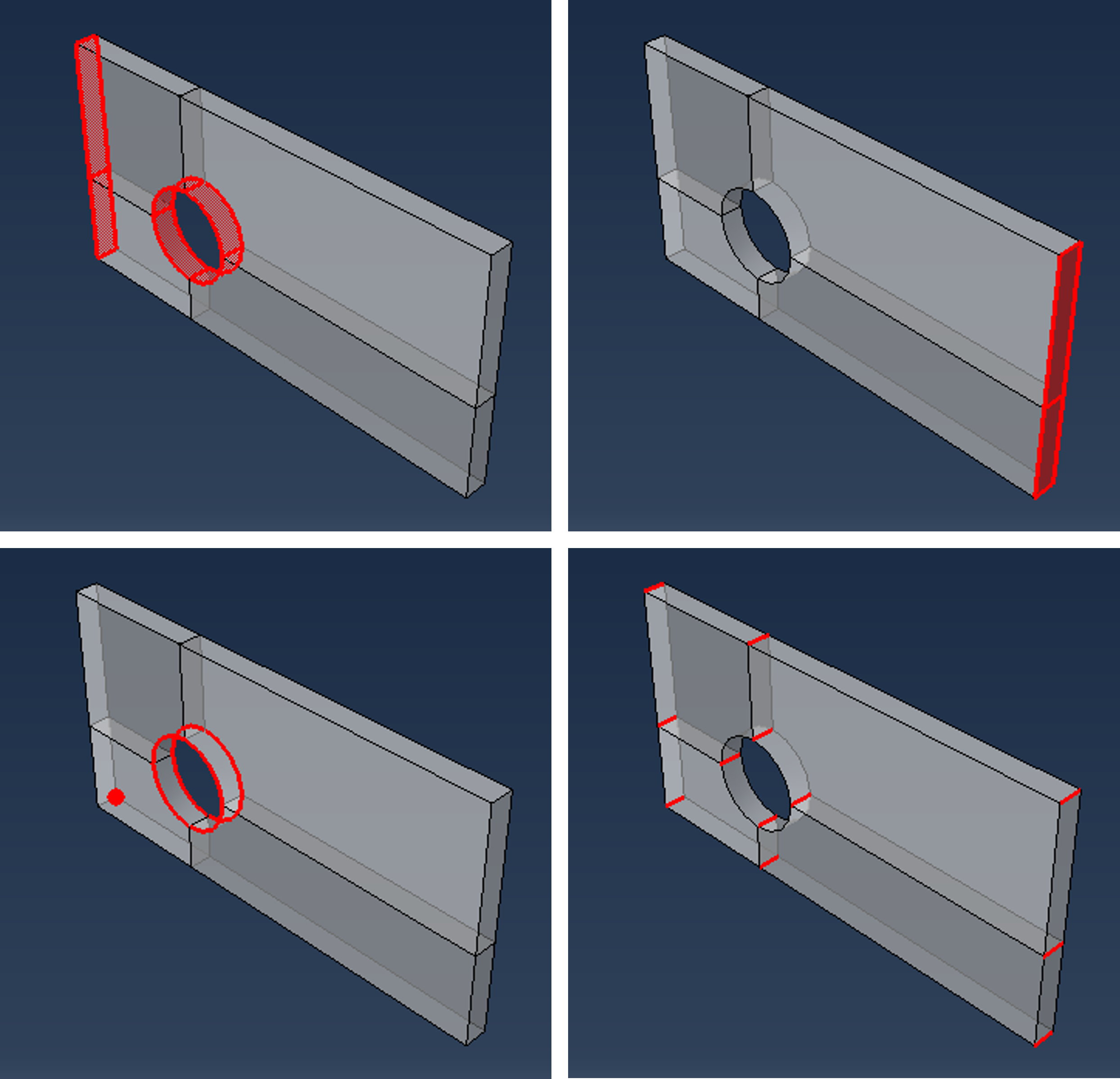
The previous method required just a datum plane, while this method requires a point and a normal. The point can be a Vertex, DatumPoint or InterestingPoint, while the normal is a straight Edge or DatumAxis.
Create a datum point at the center of the hole and return the id of it:
idp = prt.DatumPointByCoordinate( coords=(cx,cy,0)).idThen, normals are required. The following method is rather straight forward:
    normal1 = prt.edges.findAt( coordinates=((L/2.0, 0, 0),))[0]
    prt.PartitionCellByPlanePointNormal(cells=prt.cells, point=prt.datums[idp], normal=normal1)
    normal2 = prt.edges.findAt( coordinates=((0, b/2.0, 0),))[0]
    prt.PartitionCellByPlanePointNormal(cells=prt.cells, point=prt.datums[idp], normal=normal2)
Note that findAt(...) returns an EdgeArray. However, there is only one edge (if the logic of selection holds), and therefore we can pick the first edge in the array: findAt(...)[0].
Summary:
    # Partitions, Alternative 2

    idp = prt.DatumPointByCoordinate( coords=(cx,cy,0)).id
    normal1 = prt.edges.findAt( coordinates=((L/2.0, 0, 0),))[0]
    prt.PartitionCellByPlanePointNormal(cells=prt.cells, point=prt.datums[idp], normal=normal1)
    normal2 = prt.edges.findAt( coordinates=((0, b/2.0, 0),))[0]
    prt.PartitionCellByPlanePointNormal(cells=prt.cells, point=prt.datums[idp], normal=normal2)
PartitionCellByPlaneThreePoints(cells, point1, point2, point3)
Some methods of partitioning are very simple when using the GUI, while being rather involved for coding. That should, however, not prevent us from trying...
For instance, the code generated in abaqus.rpy for the session in the recording to the right is:
p = mdb.models['M1'].parts['P1']
c = p.cells
pickedCells = c.getSequenceFromMask(mask=('[#1 ]',),)
v1, e1, d1 = p.vertices, p.edges, p.datums
p.PartitionCellByPlaneThreePoints(point2=v1[9],
    point3=v1[8], cells=pickedCells,
    point1=p.InterestingPoint(edge=e1[13], rule=CENTER))
Translated to the variables used in prior scripts, removing assignments not needed and re-arranging the arguments and breaking down to something readable:
pt1 = prt.InterestingPoint(edge=prt.edges[13], rule=CENTER)
pt2 = prt.vertices[9]
pt3 = prt.vertices[8]
prt.PartitionCellByPlaneThreePoints(cells=prt.cells, point1=pt1, point2=pt2, point3=pt3)
The task is now to figure out a way to select the edge and the two vertices using some methods and logic based on geometrical features. A working solution is for example the use of getByBoundingCylinder(...) and getByBoundingSphere(...):
    edge = prt.edges.getByBoundingCylinder(center1=(cx, cy, -0.001), center2=(cx, cy, 0.001), radius=r+0.001)[0]
    vertice1 = prt.vertices.getByBoundingSphere(center=(cx+r, cy, 0), radius = 0.001)[0]
    vertice2 = prt.vertices.getByBoundingSphere(center=(cx+r, cy, h), radius = 0.001)[0]
    pt1 = prt.InterestingPoint(edge=edge, rule=CENTER)
    pt2 = vertice1
    pt3 = vertice2
    prt.PartitionCellByPlaneThreePoints(cells=prt.cells, point1=pt1, point2=pt2, point3=pt3)
Now that one partition has been made, the set of edges and vertices has changed. Hence, a new round with proper logic and selection must be written.
Modify the sketch
A simpler code can be achived by carefully planing the approach and sequence of opperations.
Review the original sketch, and replace the single circle (line 8 in the code) by two arcs as illustrated in the figure to the right. Now the solid part will have at least on vertice in the planes of partitions, for example at coordinates (cx, cy+r, 0) and at coordinates cx+r, cy, 0 and these are easilly fund and referenced for in the command PartitionCellByPlanePointNormal(point, normal, cells)
Modifications and additions are therefore:
    ...
    # ske.CircleByCenterPerimeter(center=(cx, cy), point1=(cx+r, cy))  # replaced by the following lines:
    ske.ArcByCenterEnds(center=(cx, cy), point1=(cx+r, cy), point2=(cx, cy+r), direction=CLOCKWISE)
    ske.ArcByCenterEnds(center=(cx, cy), point1=(cx, cy+r), point2=(cx+r, cy), direction=CLOCKWISE)
... # Partitions, Aleternative 3
normal = prt.edges.findAt( coordinates=((L/2.0, 0, 0),))[0]
point = prt.vertices.findAt( coordinates = ((cx, cy+r, 0),))[0]
prt.PartitionCellByPlanePointNormal(point=point, normal=normal, cells=prt.cells)
normal = prt.edges.findAt( coordinates=((0, b/2.0, 0),))[0]
point = prt.vertices.findAt( coordinates = ((cx+r, cy, 0),))[0]
prt.PartitionCellByPlanePointNormal(point=point, normal=normal, cells=prt.cells)
Creating sets and surfaces
A number of sets and surfaces must be created:
- Set: All faces at x=0: For applying boundary conditions
- Surface: All faces at x=L: For applying shear force
- Set: All faces at the hole: For results
- Set: Circular edges at the hole: For controlling the number of elements locally
- Set: All edges running through the thickness of the plate: For controlling the number of elements through the thickness
- Set: The vertices at x=0, y=0, z=0: For boundary condition preventing rigid body motions
Using various methods for the purpose of demonstration (see also Selection methods:
    ...
    # Sets and surfaces:

    from part import EdgeArray, FaceArray
    prt.Set(name='cells all', cells=prt.cells)
    faces_x0 = FaceArray([f for f in prt.faces if f.pointOn[0][0]==0.0])
    prt.Set(name='faces at x=0', faces=faces_x0)
    faces_xL = FaceArray([f for f in prt.faces if f.pointOn[0][0]==L])
    prt.Surface(side1Faces=faces_xL, name='surface at x=L')
    faces_hole = prt.faces.getByBoundingBox(cx-r, cy-r, 0.0, cx+r, cy+r, h)
    prt.Set(name='faces hole', faces=faces_hole)
    edges_hole_1 = prt.edges.getByBoundingBox(cx-r, cy-r, -0.001, cx+r, cy+r, 0.001)
    edges_hole_2 = prt.edges.getByBoundingBox(cx-r, cy-r, h-0.001, cx+r, cy+r, h+0.001)
    prt.Set(name='edges hole circ', edges=edges_hole_1+edges_hole_2)
    edges_through_z = EdgeArray([e for e in prt.edges if e.pointOn[0][2]>0.0 and e.pointOn[0][2]<h])
    prt.Set(name='edges through thickness', edges=edges_through_z)
    vertex1 = prt.vertices.findAt(coordinates=((0.0,0.0,0.0),))
    prt.Set(name='vertex 1', vertices=vertex1)
Alternatively, the procedure can be simplified using custom tools:
...
from customtools import getByPO, getByR
...
    # Sets and surfaces (using custom tools):

    prt.Set(name='cells all', cells=prt.cells)
    prt.Set(name='faces at x=0', faces=getByPO(prt.faces, x=0.0))
    prt.Surface(name='surface at x=L', side1Faces=getByPO(prt.faces, x=L))
    prt.Set(name='faces hole', faces=getByR(prt.faces, r=r))
    prt.Set(name='edges hole circ', edges=getByR(prt.edges, r=r))
    edges_through_z = EdgeArray([e for e in prt.edges if e.pointOn[0][2]>0.0 and e.pointOn[0][2]<h])
    prt.Set(name='edges through thickness', edges=edges_through_z)
    prt.Set(name='vertex 1', vertices=getByPO(prt.vertices, x=0, y=0, z=0))
Mesh
The mesh shall be controlled by defining a global seed by a parameter esize as well as the number of element through the thickness nez and the number of elements along the arcs of the hole, nec.
Note that the element type will be the default element (CD3R) as no other options are being defined in the following lines. The parameters must be added to the function arguments:
def plateWithHole(modelname, L, b, h, r, cx, cy, esize, nez, nec):
    ...
    # Mesh:

    prt.seedPart(size=esize, deviationFactor=0.1, minSizeFactor=0.1)
    prt.seedEdgeByNumber(edges=prt.sets['edges through thickness'].edges, number=nez, constraint=FINER)
    prt.seedEdgeByNumber(edges=prt.sets['edges hole circ'].edges, number=nec, constraint=FINER)
    prt.generateMesh()
Material and section
Assuming a linear elastic isotropic material defined by the modulus E and Poisson's ratio nu:
def plateWithHole(modelname, L, b, h, r, cx, cy, esize, nez, nec, E, nu):
    ...
    # Material and section:

    mat = mod.Material(name='Material-1')
    mat.Elastic(table=((E, nu), ))
    mod.HomogeneousSolidSection(name='Section-1', material='Material-1', thickness=None)
    prt.SectionAssignment(region=prt.sets['cells all'], sectionName='Section-1')
Assembly and instance
The name of the instance can just as well be identical to the name of the part when only one instance will be present in the assembly:
    ...
    # Assembly and instance

    ass = mod.rootAssembly
    ass.DatumCsysByDefault(CARTESIAN)
    ins = ass.Instance(name='P1', part=prt, dependent=ON)
Steps and loading
A shear force Fs shall be added to the end at x=L, and the variable is included as argument in the function. The step Step-1 is a general static step.
def plateWithHole(modelname, L, b, h, r, cx, cy, esize, nez, nec, E, nu, Fs):
    ...
    # Steps and loading:

    mod.DisplacementBC(name='BC-1', createStepName='Initial', region=ins.sets['faces at x=0'], u1=SET, u2=SET)
    mod.DisplacementBC(name='BC-2', createStepName='Initial', region=ins.sets['vertex 1'], u3=SET)
    mod.StaticStep(name='Step-1', previous='Initial')
    mod.SurfaceTraction(name='ShearForce', createStepName='Step-1', region=ins.surfaces['surface at x=L'],
        magnitude=Fs, directionVector=((0.0, 0.0, 0.0), (0.0, 1.0, 0.0)))
Job
Using default settings and easy bookkeeping by using the same name for the job and the model:
    ...
    # Job and results

    job = mdb.Job(name=modelname, model=modelname)
    job.submit(consistencyChecking=OFF)
    job.waitForCompletion()
Summary:
Complete script
from abaqus import *
from abaqusConstants import *
from customtools import getByPO, getByR
from part import EdgeArray

def plateWithHole(modelname, L, b, h, r, cx, cy, esize, nez, nec, E, nu, Fs):
    mod = mdb.Model(name=modelname)
    ske = mod.ConstrainedSketch(name='__profile__', sheetSize=200.0)
    ske.rectangle(point1=(0.0, 0.0), point2=(L, b))
    ske.ArcByCenterEnds(center=(cx, cy), point1=(cx+r, cy), point2=(cx, cy+r), direction=CLOCKWISE)
    ske.ArcByCenterEnds(center=(cx, cy), point1=(cx, cy+r), point2=(cx+r, cy), direction=CLOCKWISE)
    prt = mod.Part(name='P1', dimensionality=THREE_D, type=DEFORMABLE_BODY)
    prt.BaseSolidExtrude(sketch=ske, depth=h)
    del mod.sketches['__profile__']
    session.viewports['Viewport: 1'].setValues(displayedObject=prt)

    # Partitions:

    prt.PartitionCellByPlanePointNormal(
        point=getByPO(prt.vertices, x=cx, y=cy+r, z=0)[0], normal=getByPO(prt.edges, y=0, z=0)[0], cells=prt.cells)
    prt.PartitionCellByPlanePointNormal(
        point=getByPO(prt.vertices, x=cx+r, y=cy, z=0)[0], normal=getByPO(prt.edges, x=0, z=0)[0], cells=prt.cells)

    # Sets and surfaces:

    prt.Set(name='cells all', cells=prt.cells)
    prt.Set(name='faces at x=0', faces=getByPO(prt.faces, x=0.0))
    prt.Surface(name='surface at x=L', side1Faces=getByPO(prt.faces, x=L))
    prt.Set(name='faces hole', faces=getByR(prt.faces, r=r))
    prt.Set(name='edges hole circ', edges=getByR(prt.edges, r=r))
    edges_through_z = EdgeArray([e for e in prt.edges if e.pointOn[0][2]>0.0 and e.pointOn[0][2]<h])
    prt.Set(name='edges through thickness', edges=edges_through_z)
    prt.Set(name='vertex 1', vertices=getByPO(prt.vertices, x=0, y=0, z=0))

    # Mesh:

    prt.seedPart(size=esize, deviationFactor=0.1, minSizeFactor=0.1)
    prt.seedEdgeByNumber(edges=prt.sets['edges through thickness'].edges, number=nez, constraint=FINER)
    prt.seedEdgeByNumber(edges=prt.sets['edges hole circ'].edges, number=nec, constraint=FINER)
    prt.generateMesh()

    # Material and section:

    mat = mod.Material(name='Material-1')
    mat.Elastic(table=((E, nu), ))
    mod.HomogeneousSolidSection(name='Section-1', material='Material-1', thickness=None)
    prt.SectionAssignment(region=prt.sets['cells all'], sectionName='Section-1')

    # Assembly and instance

    ass = mod.rootAssembly
    ass.DatumCsysByDefault(CARTESIAN)
    ins = ass.Instance(name='P1', part=prt, dependent=ON)

    # Steps and loading:

    mod.DisplacementBC(name='BC-1', createStepName='Initial', region=ins.sets['faces at x=0'], u1=SET, u2=SET)
    mod.DisplacementBC(name='BC-2', createStepName='Initial', region=ins.sets['vertex 1'], u3=SET)
    mod.StaticStep(name='Step-1', previous='Initial')
    mod.SurfaceTraction(name='ShearForce', createStepName='Step-1', region=ins.surfaces['surface at x=L'],
        magnitude=Fs, directionVector=((0.0, 0.0, 0.0), (0.0, 1.0, 0.0)))

    # Job and results

    job = mdb.Job(name=modelname, model=modelname)
    job.submit(consistencyChecking=OFF)
    job.waitForCompletion()


plateWithHole(modelname='M1', L=100.0, b=50.0, h=5.0, r=10.0, cx=30.0, cy=20.0,
              esize=3.0, nez=4, nec=10, E=200000.0, nu=0.3, Fs=50.0)


