Shell laminate
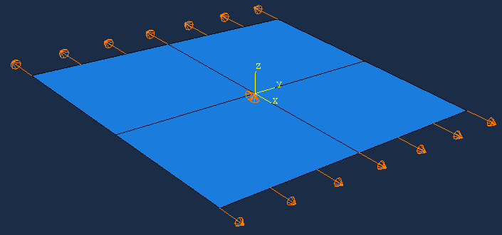
The part is made of a plane face that is partitioned such that ther exists a vertex at the middle of the laminate. Prevention of rigid body motion is maintained by boundary conditions on this vertex.
The laminate is defined as for the Solid laminate while it is implemented in the Abaqus model as a Composite Layup.
Note that the instance is moved such that the origin of the global coordinate system is at the center of the laminate.
from abaqus import *
from abaqusConstants import *
import regionToolset

def matlib(modelname):
    mod = mdb.models[modelname]
    mat = mod.Material('E-glass/Epoxy')
    mat.Density(table=((2000e-12, ), ))
    mat.Elastic(type=ENGINEERING_CONSTANTS,
        table=((40000, 10000, 10000, 0.3, 0.3, 0.3, 3800, 3800, 3400,), ))
    mat.Expansion(type=ORTHOTROPIC, table=((7E-06, 22E-06, 22E-06), ))

lam1 = [{'mat':'E-glass/Epoxy', 'ori':  0.0, 'thi': 1.0},
        {'mat':'E-glass/Epoxy', 'ori':-45.0, 'thi': 2.0},
        {'mat':'E-glass/Epoxy', 'ori':  0.0, 'thi': 1.0},
        {'mat':'E-glass/Epoxy', 'ori': 45.0, 'thi': 2.0},
        {'mat':'E-glass/Epoxy', 'ori':  0.0, 'thi': 1.0}]

def shellLaminate(modelname, L, b, laminate, esize, ex):

    t = sum([layer['thi'] for layer in laminate])

    # new model:
    mod = mdb.Model(name=modelname)

    # materials and sections:
    matlib(modelname)
    for matname in mod.materials.keys():
        mod.HomogeneousSolidSection(name=matname, material=matname, thickness=None)

    # planar shell:
    ske = mod.ConstrainedSketch(name='__profile__', sheetSize=200.0)
    ske.rectangle(point1=(0.0, 0.0), point2=(L, b))
    prt = mod.Part(name='P1', dimensionality=THREE_D, type=DEFORMABLE_BODY)
    prt.BaseShell(sketch=ske)
    del mod.sketches['__profile__']
    session.viewports['Viewport: 1'].setValues(displayedObject=prt)

    # Partitions:
    point1 = prt.InterestingPoint(edge=prt.edges.getByBoundingBox(xMax=0.0)[0], rule=MIDDLE)
    point2 = prt.InterestingPoint(edge=prt.edges.getByBoundingBox(xMin=L)[0], rule=MIDDLE)
    prt.PartitionFaceByShortestPath(faces=prt.faces, point1=point1, point2=point2)
    point1 = prt.InterestingPoint(edge=prt.edges.getByBoundingBox(yMax=0.0)[0], rule=MIDDLE)
    point2 = prt.InterestingPoint(edge=prt.edges.getByBoundingBox(yMin=b)[0], rule=MIDDLE)
    prt.PartitionFaceByShortestPath(faces=prt.faces, point1=point1, point2=point2)

    # layup:
    id = prt.DatumCsysByDefault(coordSysType=CARTESIAN).id
    layupOrientation = prt.datums[id]
    region = regionToolset.Region(faces=prt.faces)
    compositeLayup = prt.CompositeLayup(name='Layup1', elementType=SHELL, offsetType=MIDDLE_SURFACE)
    compositeLayup.Section()
    compositeLayup.ReferenceOrientation(orientationType=SYSTEM, localCsys=layupOrientation, axis=AXIS_3)
    count = 1
    for layer in laminate:
        compositeLayup.CompositePly(suppressed=False, plyName='Ply-'+str(count), region=region,
            material=layer['mat'], thicknessType=SPECIFY_THICKNESS, thickness=layer['thi'],
            orientationType=SPECIFY_ORIENT, orientationValue=layer['ori'] )
        count = count + 1

    # Mesh:
    prt.seedPart(size=esize, deviationFactor=0.1, minSizeFactor=0.1)
    prt.generateMesh()

    # Assembly:
    ass = mod.rootAssembly
    ass.DatumCsysByDefault(CARTESIAN)
    ins = ass.Instance(name='P1', part=prt, dependent=ON)
    ass.translate(instanceList=('P1', ), vector=(-L/2.0, -b/2.0, 0.0))

    # Step:
    mod.StaticStep(name='Step-1', previous='Initial')

    # Load case (uniform strain)
    dux = ex*L
    region = ass.Set(name='xa', edges = ins.edges.getByBoundingBox(xMax=-L/2.0))
    mod.DisplacementBC(name='xa', createStepName='Step-1', region=region, u1=-dux/2.0)
    region = ass.Set(name='xb', edges = ins.edges.getByBoundingBox(xMin=L/2.0))
    mod.DisplacementBC(name='xb', createStepName='Step-1', region=region, u1=dux/2.0)

    # Preventing rigid body motions by fixing the vertex in the midle:
    region = ass.Set(name='vertex center', vertices = ins.vertices.findAt(coordinates=((0,0,0),)))
    mod.DisplacementBC(name='rb', createStepName='Step-1', region=region, u2=0, u3=0)

    # Added field output
    mod.FieldOutputRequest(name='F-Output-2', createStepName='Step-1', variables=('S', 'E', 'SE', 'SF'),
        layupNames=('P1.Layup1', ), layupLocationMethod=ALL_LOCATIONS, rebar=EXCLUDE)

    # Job and results
    job = mdb.Job(name=modelname, model=modelname)
    job.submit(consistencyChecking=OFF)
    job.waitForCompletion()
    odb = session.openOdb(name=modelname+'.odb')

shellLaminate(modelname='SLam1', L=100.0, b=100.0, laminate=lam1, esize=10, ex=0.01)
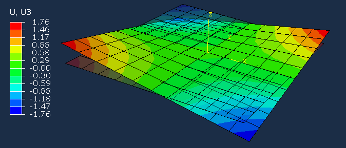
Example-1
Resulting deformation using the script as given is comparable to the corresponding Solid laminate.
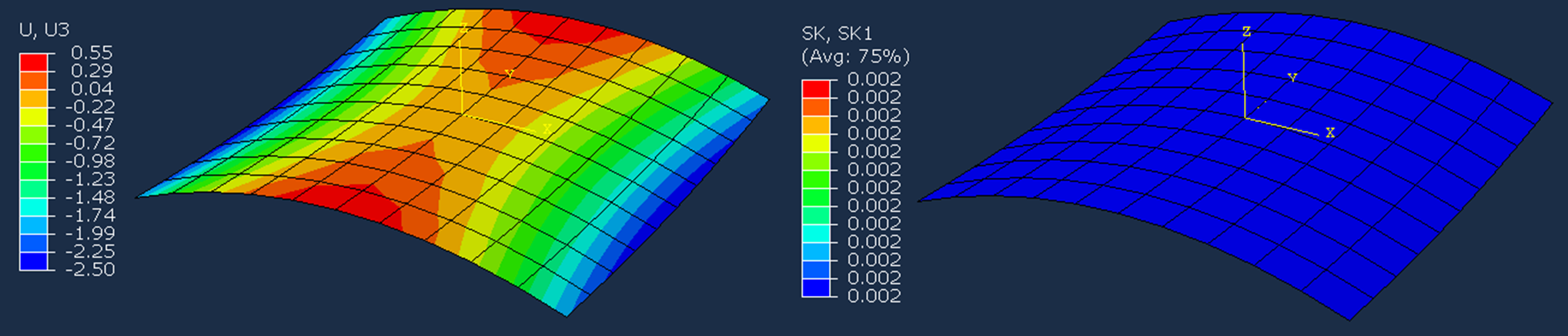
Example-2
A constant curvature along x can be imposed by adding rotation on the edges at x = -L/2 and x = +L/2
For consistency with the laminate theory, the rotation at x = -L/2 must be negative while the same positive value is applied at x = +L/2.
Add a symmetric laminate and add an argument Kx to the function:
lam2 = [{'mat':'E-glass/Epoxy', 'ori':  0.0, 'thi': 1.0},
        {'mat':'E-glass/Epoxy', 'ori': 90.0, 'thi': 2.0},
        {'mat':'E-glass/Epoxy', 'ori':  0.0, 'thi': 1.0}]

def shellLaminate(modelname, L, b, laminate, esize, ex, Kx):
Modify the load case:
    # Load case (uniform strain and curvature along x)
    dux = ex*L
    ur2 = 0.5*Kx*L
    region = ass.Set(name='xa', edges = ins.edges.getByBoundingBox(xMax=-L/2.0))
    mod.DisplacementBC(name='xa', createStepName='Step-1', region=region, u1=-dux/2.0, ur2=-ur2)
    region = ass.Set(name='xb', edges = ins.edges.getByBoundingBox(xMin=L/2.0))
    mod.DisplacementBC(name='xb', createStepName='Step-1', region=region, u1=dux/2.0, ur2=ur2)
Function call:
shellLaminate(modelname='SLam2', L=100.0, b=100.0, laminate=lam2, esize=10, ex=0.0, Kx=0.002)
Results where the output paramter SK1 is the curvature $\kappa_x$
More on the theory in Shell elements and laminate theory


