Materials selection
The materials selection process for components and products can be extremely involved and complex. The fundamental idea is however profoundly simple, namely to…
…choose the most appropriate material(s) from a set of possible candidates.
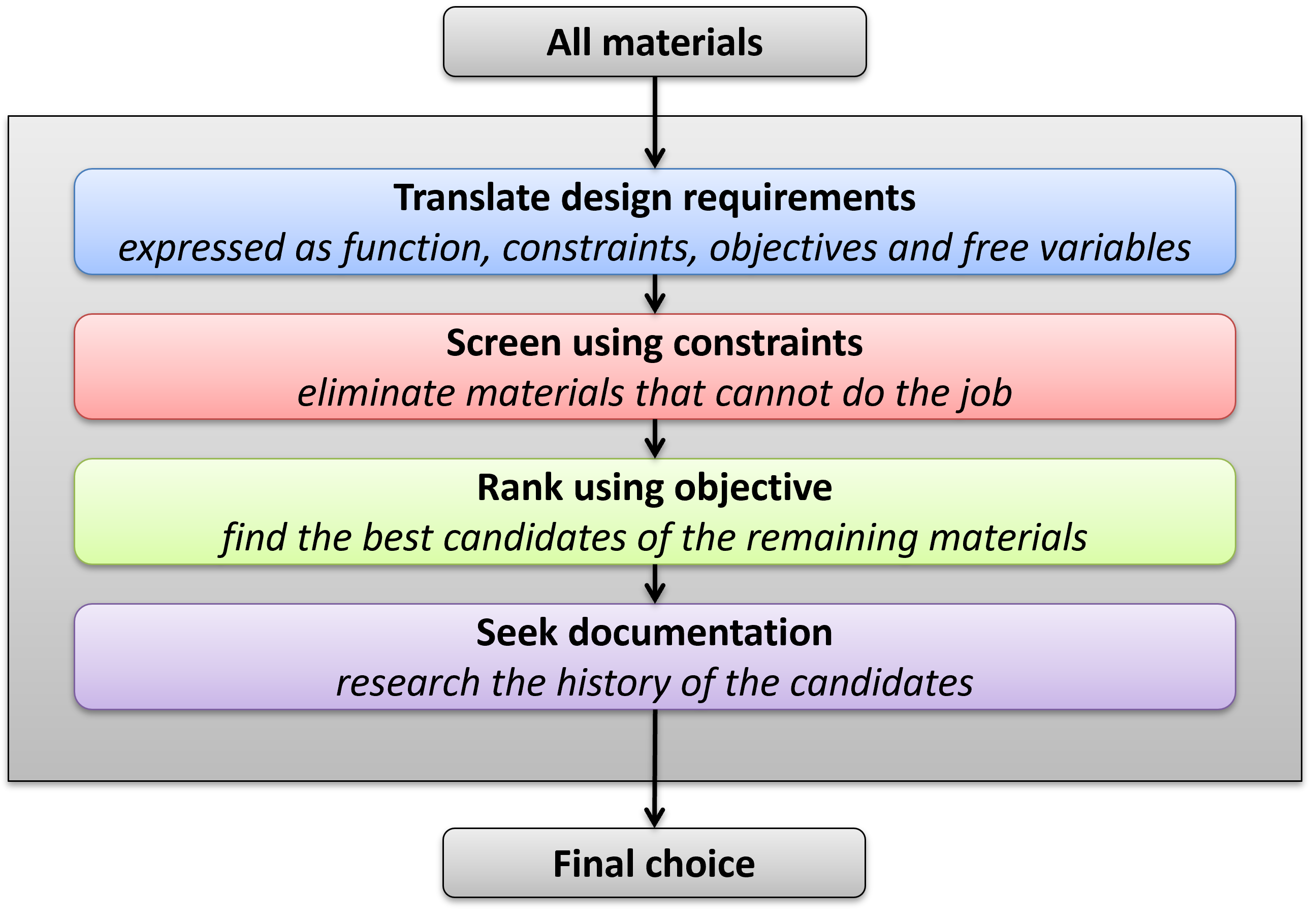
There are various frameworks for systematic materials selection processes, reflecting variations in approaches, industry specific focuses and more. The different theories do however encompass common elements:
Function: the specific purpose or role that a component, system, or product is intended to perform. It is the fundamental reason for the existence and determines what it needs to do, how it interacts with other components or systems, and what performance criteria it must satisfy.
Constraints: the limitations or restrictions that the design must adhere to. These constraints define the boundaries within which the design solution must be developed. They can be physical, economic, environmental, social, or regulatory in nature and are essential in guiding the design process to ensure the final product is feasible, safe, cost-effective, and compliant with standards.
Objectives: the objective criteria that enable differentiation and ranking of materials for the application. The objectives can usually be translated to objective functions that returns material indices that shall be maximized or minimized within the constraints.
Free variables: parameters and features not limited by the constraints, i.e. all essential variables the designer is free to choose.
Elimination: most materials can often be eliminated based on simple single-variable criteria, such as required service temperature and functional properties intrinsically related to for instance a material category or crystalline structure.
Ranking: apply the objective function(s) to sort the remaining potential candidates.
Verification and qualification: a material ranked as the best candidate may have issues not disclosed during the previous stages. Thus, a comprehensive investigation of the specific material should be conducted.
Example: Electrical cable
The function of the electrical cable is, unsurprisingly, to conduct electrical current. Constraints for this case include the length $L_0$ while the resistance must be less than $R_0$. The cross-section area of the cable and the choice of material are free variables. The objective for the case is simple: the cable shall be as thin as possible. Materials that can be eliminated up-front are those being categorized predominantly as insulators, such as polymers and ceramics. The objective function can now be developed:
$$R<R_0 \Rightarrow \frac{L_0}{A}r_e < R_0 \Rightarrow A > \big( \frac{L_0}{R_0} \big) \big( r_e \big)$$where $r_e$ is the resistivity of the material.
Minimum cross-section area $A$ is obtained by minimizing the part of the expression not bound by constraints:
$$ \min(A) \Rightarrow \min(r_e)$$The optimum material choice is therefore silver ($r_e = 0.16 \text{ n}\Omega$) followed by copper ($r_e = 0.17 \text{ n}\Omega$).
The higher performance of silver is minor, while the price of silver exceeds the price of copper by a factor of about 100:1, which is the obvious reason for why copper and not silver is found in most cables.
In another application, the objective is to minimize the mass of the cabel:
$$ m = L_0 A \rho$$Substituting $A$ from previous expression:
$$ m > \big( \frac{L_0^2}{R_0} \big) \big( r_e \rho \big) $$The product of resistivity and density should therefore be minimized. Numerical results for high-conductive metals:
materials = [{'Name':'Silver',  're':1.59E-8, 'rho':10490}, {'Name':'Copper',  're':1.68E-8, 'rho': 8960},
             {'Name':'Gold',    're':2.44E-8, 'rho':19300}, {'Name':'Aluminum','re':2.65E-8, 'rho': 2700},
             {'Name':'Calcium', 're':3.36E-8, 'rho': 1550}, {'Name':'Rhodium', 're':4.33E-8, 'rho':12410},
             {'Name':'Tungsten','re':5.60E-8, 'rho':19250}, {'Name':'Zinc',    're':5.90E-8, 'rho': 7140},
             {'Name':'Cobalt',  're':6.24E-8, 'rho': 8900}, {'Name':'Nickel',  're':6.99E-8, 'rho': 8908},
             {'Name':'Lithium', 're':9.28E-8, 'rho':  535}, {'Name':'Iron',    're':9.70E-8, 'rho': 7860} ]

ind_copper = materials[1]['re']*materials[1]['rho']
mlist = sorted( [(m['re']*m['rho']/ind_copper, m['Name']) for m in materials] )
for m in mlist:
    print('{:8}: {:.2f}'.format(m[1],m[0]))
The mass of a cable made of Lithium or Calcium is approximatly one third of a copper cable. There are, however, all kinds of challenges with those materials, something that would have been reveald during qualification, or preferably during initial elimination. For instance, a totally reasonable requirement along the lines of shall not explode in contact with water will make these two materials not relevant.
Aluminum enables a weight reduction to about one half of a copper cable, and is used extensively in overhead power lines where light weight design is important for obvious reasons.
Materials selection and lightweight design
The primary objective in lightweight design is, by definition, minimum weight. In most cases, there will however be additional objectives frequently in conflict with the primary one, low cost being and obvious example.
Common structural elements and members under idealized conditions provide useful introductory examples for the material selection process. However, real-life scenarios typically involve additional complexities, conflicting objectives, and more advanced considerations including the interaction between materials selection and shapes.
Tie rods | Beams | Panels | Struts and columns | Springs
Tie rods

Function: A tie rod is a structural component designed to transfer and withstand primarily tensile loads, maintaining the connection between different parts of a structure or system.
General constraints: We may assume that the length $L$ is decided and the maximum design force $F$ is known. That is:
$$L = L_0$$$$F = F_0$$Free variables: The cross section area $A$ and choice of material.
Simplifications: The end connectors will be totally ignored and the problem is one-dimentional in terms of stress, while the mass of the component is simply the density of the material multiplied with the volume where a constant cross section area is assumed:
\begin{equation} m =\rho L_0 A \tag{1} \end{equation}Stiffness based design of a tie rod
Constraint: The extension $\Delta L$ shall be limited to a given value $\Delta L_0$, which leads to a required minimum cross section area:
$$\Delta L \le \Delta L_0 \Rightarrow \varepsilon L_0 \le \Delta L_0 \Rightarrow \frac{\sigma}{E} L_0 \le \Delta L_0 \Rightarrow \frac{F_0}{AE} L_0 \le \Delta L_0 \Rightarrow$$\begin{equation} A \ge \frac{F_0 L_0}{\Delta L_0 E} \tag{2} \end{equation}Substituting $A$ from (2) into (1):
\begin{equation} m \ge \bigg(\frac{F_0 L_0^2}{\Delta L_0}\bigg) \bigg(\frac{\rho}{E}\bigg) \tag{3} \end{equation}Minimum mass implies:
$$ \min(m) \Rightarrow \min \bigg(\frac{\rho}{E}\bigg) \Rightarrow$$\begin{equation} \max \bigg(\frac{E}{\rho}\bigg) \tag{4} \end{equation}Strength based design of a tie rod
Constraint: The tensile stress must be less than the failure strength $\sigma_f$:
$$\sigma \le \sigma_f \Rightarrow \frac{F_0}{A} \le \sigma_f \Rightarrow$$\begin{equation} A \ge \frac{F_0}{\sigma_f} \tag{5} \end{equation}Substituting $A$ from (5) into the expression for the mass (1):
\begin{equation} m \ge \bigg(L_0 F_0 \bigg) \bigg(\frac{\rho}{\sigma_f}\bigg) \tag{6} \end{equation}Minimum mass implies:
$$ \min(m) \Rightarrow \min \bigg(\frac{\rho}{\sigma_f}\bigg) \Rightarrow$$\begin{equation} \max \bigg(\frac{\sigma_f}{\rho}\bigg) \tag{7} \end{equation}Beams
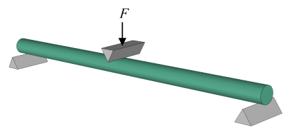
Function: A beam is a structural component designed to transfer and withstand primarily bending and torosional loads
General constraints: We may assume that the length $L$ is decided and the maximum design moment$M$ is known. That is:
$$L = L_0$$$$M = M_0$$Free variables: The cross section area $A$ and choice of material.
Simplifications: the cross-section is solid and constant along the length and with fixed proportionality. For example, the ratio of height to width of a rectangular cross section is a constraint:
$$\frac{h}{b} = a_0$$Furthermore, transverse shear stress i neglected.
Stiffness based design of a beam
Constraint: The curvature $\kappa$ shall be limited to a given value $\kappa_0$,
$$\kappa \le \kappa_0 \Rightarrow$$$$\frac{M_0}{EI} \le \kappa_0 \Rightarrow \frac{12M_0}{Ebh^3} \le \kappa_0 \Rightarrow \frac{12M_0}{Ea_0h^4} \le \kappa_0 \Rightarrow$$\begin{equation} h \ge \bigg( \frac{12M_0}{Ea_0 \kappa_0} \bigg)^{1/4} \tag{8} \end{equation}The mass of the beam is
\begin{equation} m = L_0 b h \rho = L_0 a_0 h^2 \rho \tag{9} \end{equation}Combining (8) and (9):
\begin{equation} m \ge \bigg( \frac{12M_0 L_0^2 a_0}{\kappa_0} \bigg)^{1/2} \bigg( \frac{\rho}{E^{1/2}} \bigg) \tag{10} \end{equation}Minimum mass implies:
$$ \min(m) \Rightarrow \min \bigg(\frac{\rho}{E^{1/2}}\bigg) \Rightarrow$$\begin{equation} \max \bigg(\frac{E^{1/2}}{\rho}\bigg) \tag{11} \end{equation}Strength based design of a beam
Constraint: The stress must be less than a fraction of the failure strength $\sigma_f$ expressed by a safety factor $S_f$:
$$ S_f \cdot \sigma \le \sigma_y \Rightarrow$$$$ S_f \frac{M_0}{I}\frac{h}{2} \le \sigma_f \Rightarrow S_f \frac{12M_0}{bh^3}\frac{h}{2} \le \sigma_f \Rightarrow S_f \frac{6M_0}{bh^2} \le \sigma_f \Rightarrow S_f \frac{6M_0}{a_0 h^3} \le \sigma_f \Rightarrow$$\begin{equation} h \ge \bigg( \frac{6 S_f M_0}{a_0 \sigma_f} \bigg)^{1/3} \tag{12} \end{equation}The mass is
\begin{equation} m = L_0 b h \rho = L_0 a_0 h^2 \rho \tag{13} \end{equation}Combining (12) and (13)
\begin{equation} m \ge \bigg( 6 S_f M_0 L_0^{3/2} a_0^{1/2} \bigg)^{2/3} \bigg( \frac{ \rho}{\sigma_f^{2/3}} \bigg) \tag{14} \end{equation}Minimum mass implies:
$$ \min(m) \Rightarrow \min \bigg(\frac{\rho}{\sigma_f^{2/3}}\bigg) \Rightarrow$$\begin{equation} \max \bigg(\frac{\sigma_f^{2/3}}{\rho}\bigg) \tag{15} \end{equation}Panels
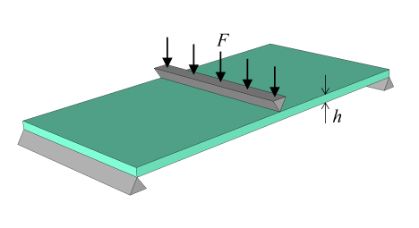
Function: A panel is a structural component designed to transfer and withstand primarily flexural loads. It differs from a beam by having a fixed width while the thickness is a free variable.
General constraints: We may assume that the length $L$ and width $b$ is decided and the maximum design moment$M$ is known. That is:
$$L = L_0$$$$b = b_0$$$$M = M_0$$Free variables: The thickness $h$ and choice of material.
Simplifications: the cross-section is solid and constant along the length, and both transverse shear stress and Poisson's effects are ignored.
Stiffness based design of a panel
Constraint: The curvature $\kappa$ shall be limited to a given value $\kappa_0$,
$$\kappa \le \kappa_0 \Rightarrow$$leading to a solution for the mass:
\begin{equation} m \ge \bigg( \frac{12M_0 L_0^3 b_0^3}{\kappa_0} \bigg)^{1/3} \bigg( \frac{\rho}{E^{1/3}} \bigg) \tag{16} \end{equation}Thus, the optimum solution is found by
\begin{equation} \max \bigg(\frac{E^{1/3}}{\rho}\bigg) \tag{17} \end{equation}Strength based design of a panel
Constraint: The stress must be less than failure strength $\sigma_f$:
$$\sigma \le \sigma_y \Rightarrow$$leading to a solution for the mass:
\begin{equation} m \ge \bigg( 6 S_f M_0 L_0^2 b_0 \bigg)^{1/2} \bigg( \frac{ \rho}{\sigma_f^{1/2}} \bigg) \tag{18} \end{equation}and the optimum solution is found by
\begin{equation} \max \bigg(\frac{\sigma_f^{1/2}}{\rho}\bigg) \tag{19} \end{equation}Struts and columns

A struts and columns are structural elements designed to support and withstand compressive forces that may lead to two principle failure modes:
- Buckling due to elastic instability.
- Compressive material failure, or crushing.
Assumption: the cross section of the member is solid and homogeneous, equivalent to a beam.
An optimum material choice for lightweight design when buckling is the governing failure mode is found by
\begin{equation} \max \Big(\frac{E^{1/2}}{\rho}\Big) \tag{20} \end{equation}while minimum weight with respect to compressive material failure mode is obtained by
\begin{equation} \max\Big( \frac{\sigma_f}{\rho} \Big) \tag{21} \end{equation}where $\sigma_f$ represents the relevant comressive strength of the material.
See the case study Lightweight column for a comprehensive derivation of relations along with numerical examples.
Springs
The function of a spring is to store elastic energy. A lightweight spring should be optimized by maximizing the strain energy per. mass. The material choice should therefore be selected based on
\begin{equation} \max \Big( \frac{\sigma_f^2 }{E \rho}\Big) \tag{22} \end{equation}where $\sigma_f$ is the relevant material strength or elastic limit.
In principle, the most effective configuration of a spring is when the entire cross-section and length are exposed to a uniform state of stress (a). In this case the entire volume will be exposed to maximum stress and strain, where the total strain energy for a linear elastic material is
\begin{equation} U = \frac{1}{2} \frac{\sigma^2}{E} V \tag{23} \end{equation}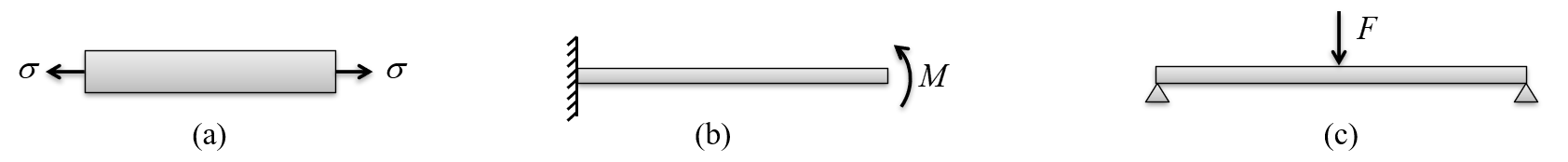
However, this solution only works when using materials with very low stiffness and high elastic elongation, i.e. rubbers. Therefore, springs are typically constructed such that the primary deformation mechanism is bending of slender cross-sections with a uniform bending moment (b). This is the primary mode of loading in both extension/compression of coil springs and in torsion of coil springs.
Consider the cantilever beam (b) having length $L$, width $b$ and thickness $h$ subjected to the moment $M$. The rotation at $x = L$ is
$$ \theta = \frac{ML}{EI}$$such that
$$ M = \frac{EI}{L} \theta$$The strain energy for a given rotation is
$$ U = \int_0^{\theta} M d\theta = \int_0^{\theta} \frac{EI}{L} \theta d\theta = \frac{1}{2} \frac{EI}{L} \theta^2$$and by substituting the rotation,
$$ U = \frac{1}{2} \frac{EI}{L} \bigg(\frac{ML}{EI}\bigg)^2 = \frac{M^2 L}{2EI}$$Maximum bending stress is
$$\sigma = \frac{M}{I}z = \frac{M}{I} \frac{h}{2}$$and therefore
$$ M = \frac{2 \sigma I}{h} \Rightarrow M^2 = \frac{4 \sigma^2 I^2}{h^2}$$Eventually, the total strain energy is
$$ U = \frac{M^2 L}{2EI} = \frac{2 \sigma^2 I L}{E h^2} = \frac{2 \sigma^2 b h^3 L}{12 E h^2} = \frac{\sigma^2 b h L}{6 E } $$or simply.
\begin{equation} U = \frac{1}{6} \frac{\sigma^2}{E} V \tag{24} \end{equation}The maximum strain energy density (energy per volume) is therefore
$$\frac{1}{6} \frac{\sigma_f^2}{E}$$while the strain energy per mass becomes
$$\frac{1}{6} \frac{\sigma_f^2}{E\rho}$$The energy in a leaf spring configured as a freely supported beam (c) subjected to a center load $F$ is
\begin{equation} U = \frac{1}{18} \frac{\sigma^2}{E} V \tag{25} \end{equation}Hence, the leaf spring is significantly less efficient than coil springs.
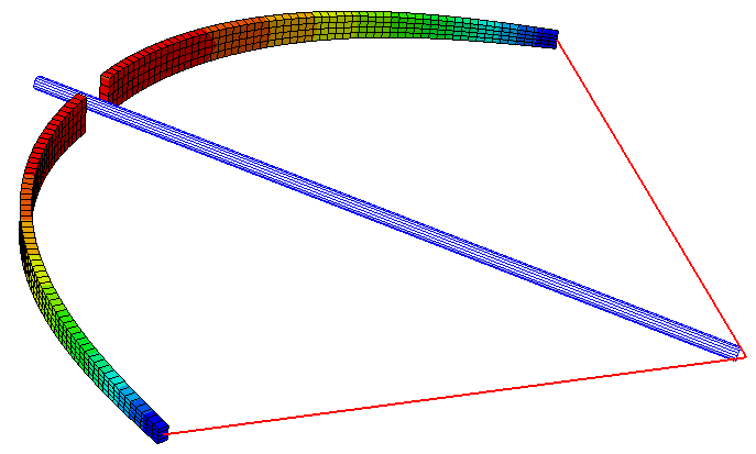
Relevant case study: Crossbow


