Assumptions for Laminate Theory
The following assumptions are fundamental to the Classical Laminate Theory (CLT):
1 Perfectly bonded layers
All layers are assumed to be perfectly bonded without any separation or slippage between them. In cases where separation between layers occurs, either due to initial adhesion issues or loading-induced failures like delamination, thet theory is no longer applicable and will require alternative analysis methods.
2 Homogeneous layers
Each layer is homogeneous. A homogeneous layer possesses uniform properties across both its plane and thickness. For instance, a fiber composite with evenly distributed fibers is considered homogeneous at the macro scale. However, if fibers are clustered or otherwise unevenly distributed, the layer may no longer be considered homogeneous, affecting the analysis accuracy.
3 Material properties of layers
Materials of individual layers can be isotropic, transversely isotropic, or orthotropic. Hence, general anisotropic materials are not applicable.
4 Plane stress condition
Each layer is assumed to be in a state of plane stress, simplifying the analysis by neglecting out-of-plane stresses.
Hooke's law expressed in the global coordinate system is reduced to
\begin{equation} \begin{bmatrix} \sigma_x \\ \sigma_y \\ \tau_{xy} \end{bmatrix}= \begin{bmatrix} Q_{xx} & Q_{xy} & Q_{xs} \\ Q_{xy} & Q_{yy} & Q_{ys} \\ Q_{xs} & Q_{ys} & Q_{ss} \end{bmatrix} \begin{bmatrix} \varepsilon_x \\ \varepsilon_y \\ \gamma_{xy} \end{bmatrix} \tag{1} \end{equation}However, localized three-dimensional stress states will usually be present at joints, transitions, and boundary regions of the shell structure. For example, an elastic mismatch between layers with differing fiber orientations can generate transverse shear stresses and normal stresses through the laminate thickness, particularly at free edges, as illustrated in Figures 1 and 2.
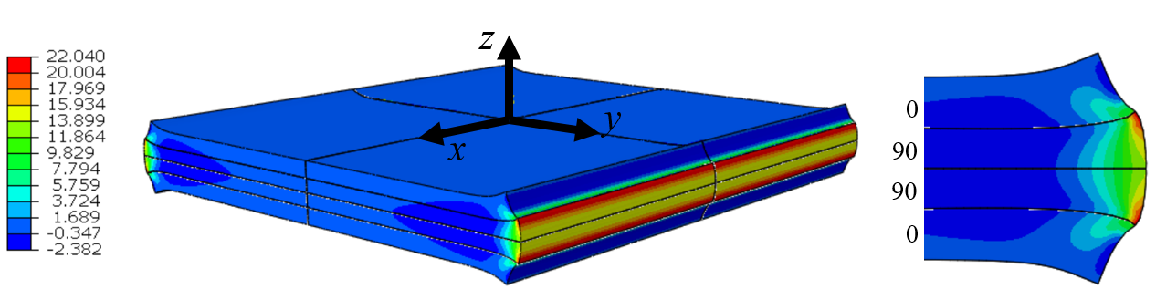
Figure-1: Through the thickness stress $\sigma_z$ at the free edges of a laminate [0/90/90/0] subjected to a tensile loading in the $x$-direction.

Figure-2: Through the thickness stress $\tau_{yz}$ at the free edges of a laminate [0/90/90/0] subjected to a tensile loading in the $x$-direction.
More on this topic in the case study Free edge effects of laminates
5 Kirchhoff assumptions
The laminate deformation follows the Kirchhoff assumptions, implying that:
- Normals to the midplane remain straight and perpendicular to the deformed midplane after deformation.
- Normals to the midplane do not change in length during deformation.
The displacements at a position $z$ through the thickness are related to the midplane displacements and rotations of the midplane expressed by:
\begin{equation} \begin{aligned} &u(x,y,z) = u_0(x,y)-z \frac{\partial w_0}{\partial x} \\ &v(x,y,z) = v_0(x,y)-z \frac{\partial w_0}{\partial y} \\ &w(x,y)=w_0(x,y) \end{aligned} \tag{2} \end{equation}where $u$, $v$ and $w$ are the displacements in $x$, $y$ and $z$ directions respectively, and $u_0$, $v_0$ and $w_0$ are the displacements of the reference plane.
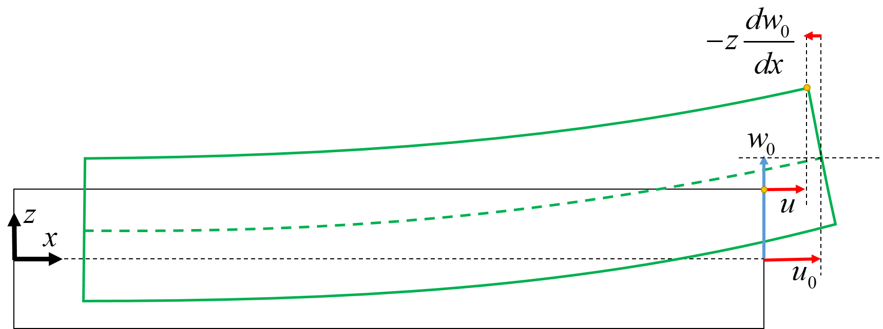
Figure-3: Kirchoff assumption
As the thickness becomes large relatively to the other characteristic dimensions of the laminate, the Kirchoff assumptions become less realistic.
Illustrated example of the deformation according to the Kirchoff assumptions from the Plot gallery


